
Form milling is a precision machining technology. It uses special profile tools to directly copy shapes onto a workpiece. This method is great for complex surfaces and producing parts in large batches. This guide explains its definition, how it works, tool types, pros, and cons. It also covers challenges, uses, and comparisons to offer practical advice.
What is Form Milling?
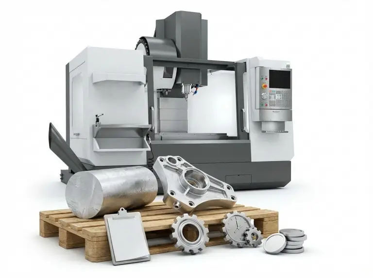
Form milling is a precise milling process. It uses special tools to make complex profiles and shapes. This process is vital in industries like aerospace, automotive, and medical. It allows for the efficient creation of precise parts. Form milling uses cutters with specific shapes. These cutters directly copy their profiles onto the workpiece.
It is a machining process that uses a milling cutter with a specific profile. This tool directly copies its shape onto the workpiece, like a reverse engraving. The method depends on the tool’s geometric shape to create the final profile. It does not rely on complex motion paths. The process focuses on using special profile cutting tools to shape complex surfaces. Unlike other general milling methods, form milling can complete detailed shapes in a single pass. This ensures high precision and consistency.
Form milling is a “forming method,” where the final shape depends on the tool’s geometry rather than the movement path between tool and workpiece. This sets it apart from other machining methods. For example, the “generating method,” such as hobbing, forms shapes through continuous relative motion—like creating involute gears. The “trajectory method,” including CNC profile milling, uses programmed tool paths and standard cutters to scan the surface layer by layer. Form milling is more efficient and specific, making it ideal for producing many identical profiles. In comparison, generating and trajectory methods offer more flexibility for shapes with variable details, such as gear profiles with different parameters.
What is the Working Principle of Form Milling?
The working principle of form milling is based on a precise interaction. The tool and the workpiece interact, using special cutters to make complex shapes. The process begins by choosing a cutter that matches the needed shape. This choice is optimized based on the workpiece material and needs. Then, the cutter is aligned with the workpiece. The milling machine rotates the cutter while the workpiece feeds into it. This creates relative motion. In projects with hard materials like titanium alloys, this principle ensures precise surface forming.
Process Flow Analysis
The tool profile and workpiece profile have a mirror relationship. This means a convex tool shape creates a concave workpiece shape, and the reverse is also true. The cutting motion uses the milling cutter’s rotation as the main movement. The workpiece feeds along an axial or radial direction as a secondary motion. The tool shape in form milling is directly copied onto the workpiece. In our practice at Yonglihao, we ensure alignment is precise. This helps avoid errors caused by being offset.
- Tool profile mirroring: A convex cutter makes a concave workpiece. This ensures a precise match.
- Main motion: The milling cutter rotates at high speed. This provides the cutting force.
- Feed motion: The workpiece moves in a straight line. This transfers the shape.
Key Cutting Parameters
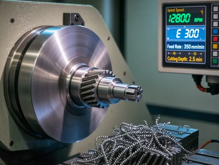
Speed, feed rate, and depth of cut directly affect form precision. They also impact surface roughness. High speed can improve efficiency but creates more heat. This can lead to increased roughness. A moderate feed rate balances productivity and quality. A shallow depth of cut reduces vibration and improves precision. Process rigidity is very important. The large contact area places high demands on machine tools and fixtures. In our batch production, increasing rigidity has lowered the risk of chatter.
- Speed influence: Too much speed can easily cause heat-related warping. We suggest adjusting speed based on the material (e.g., 200-300m/min for steel).
- Feed rate: A rate of 0.1-0.3mm per tooth ensures a finish of Ra < 1.6μm.
- Depth of cut: Use shallow layers in multiple passes. This avoids overloading the machine.
What is a Form Milling Cutter?
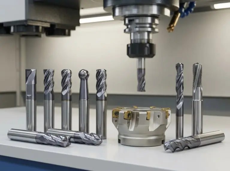
Form milling cutters are the core tools of this process. They are designed in special profile forms to help make complex shapes. We have many types and can also customize them. In mold projects, custom tools help create precise cavities.
A form milling cutter is a special profile tool. Its shape exactly matches the needed workpiece profile. Its unique feature is the relief or back-off structure. Grinding the tooth face provides a relief angle. This ensures that after resharpening the rake face, the cross-sectional shape does not change. This guarantees that machined profiles stay consistent. During manufacturing, High-Speed Steel (HSS) or carbide is usually used. The process emphasizes precision to avoid any errors.
Common Types of Form Milling Cutters
Form milling cutters come in many types. Each type is made for specific tasks.
- Concave Cutters: These are used for machining convex semicircular profiles. Their tooth design ensures even cutting and helps avoid stress points.
- Convex Cutters: These are used for machining concave semicircular profiles. They work well for deep concave features and provide a high surface finish.
- Corner Rounding Cutters: These are used to round the edges of a workpiece into a quarter circle. They come in many radius options to match different designs.
- Gear Cutters: These are disc-shaped module cutters. They are used for machining gear tooth profiles, like involute shapes. Modules range from M0.5 to M20.
- Combination/Non-Standard Form Milling Cutters: These are custom tools for specific part drawings. They combine elements like V-shapes and fillets.
Tool Materials
The choice of tool material affects performance and lifespan. It is crucial to choose the correct tool material.
- High-Speed Steel (HSS): HSS has good toughness and is suitable for making complex shapes. It is the main material for form milling cutters and is easy to resharpen.
- Carbide: Carbide is used for machining very hard materials or for high-speed work. It is typically used in inserts or as small solid carbide cutters. It provides great durability.
What are the Pros and Cons of Form Milling?
Form milling offers precision and versatility. It requires little extra work for complex parts, which reduces costs.
Main Advantages
Form milling is highly efficient. It can machine complex surfaces in a single pass. This avoids multiple steps like roughing, semi-finishing, and finishing. It is ideal for mass production and cuts down on setup time. The process has good consistency because it relies on the tool’s shape. This reduces errors from operators and machines. It results in high part interchangeability, especially for standard parts. The equipment needs are low. Ordinary three-axis milling machines can create complex profiles. This means no five-axis linkage is needed, which lowers investment costs.
- High efficiency: A single pass can complete surfaces. For example, a single-pass time can be less than 5 minutes per piece, which is faster than multi-pass methods.
- Good consistency: The shape is fixed, and tolerance is controlled within ±0.01mm. This ensures quality across a large batch.
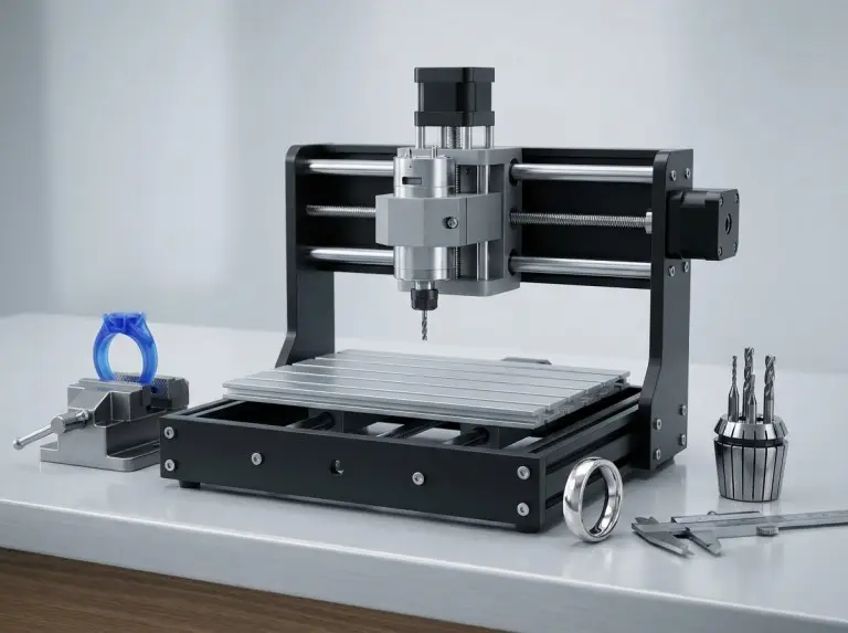
- Low equipment threshold: It is compatible with three-axis machines. This makes it suitable for small and medium factories and offers strong scalability.
Limitations and Disadvantages
Tool costs are high. Customization is expensive, and design cycles are long. It usually takes 2-4 weeks to prepare. The process has poor flexibility. It is very specific, with one tool for one shape. This makes it unsuitable for producing small batches of many different items. The cutting force is large. A large contact area can lead to vibration, causing surface chatter. In small-batch projects, these disadvantages are greater. Backup tools may be needed, which increases inventory costs.
- High tool costs: Customization is expensive, and design cycles are long.
- Poor flexibility: It is very specific; one tool makes one shape. This is not good for small batches.
- Large cutting force: The large contact area is prone to vibration.
Common Challenges and Coping Strategies in Form Milling
Form milling is efficient, but it has challenges. These include vibration, chip removal, and surface quality.
Vibration and Chatter
The main cause of vibration is a long cutting edge contact. This leads to large changes in cutting force. This affects surface finish and precision, especially with long contact areas in form machining. A lack of system rigidity makes the problem worse. This can be due to an aging machine or loose fixtures. Coping strategies include reducing speed by 10-20% and increasing the feed rate. Using unequal tooth pitch cutters and clamping the workpiece more rigidly also helps. In aerospace part machining, using unequal tooth pitch tools reduced chatter. This improved the surface Ra value. Further analysis includes adjusting speed based on material resonance. An unequal tooth pitch design breaks up periodic force waves. Hydraulic fixtures can improve clamping rigidity and reduce small movements.
- Cause: Large contact area and force changes cause self-excited vibration. This includes matching the resonance frequency.
- Solution: Optimize speed, strengthen fixtures, use damping materials, and monitor vibration with sensors.
Chip Evacuation Difficulties (Chip Evacuation)
Chip removal problems happen when deep grooves or enclosed profiles trap chips. This leads to heat buildup and tool damage. Chip buildup increases friction, which can cause surface burns or edge chipping. In complex tooth profiles, tight chip flow paths make the problem worse. Solutions include using high-pressure coolant (over 50 bar) and improving tool chip pocket design. This can mean widening pocket openings or adding helix angles. In gear projects, high-pressure cooling systems improved chip removal. This extended tool life by 30%. Detailed solutions include grading coolant pressure, from low-pressure flushing to high-pressure penetration. Chip pocket design should consider chip types (continuous or broken). Vacuum chip suction can also assist.
- Cause: Complex profiles block chip flow. Groove depth and angle also have an effect.
- Solution: Use high-pressure cooling, a wide chip pocket design, and clean the machine regularly.
Surface Finish Not Up to Standard
A poor surface finish is usually caused by a built-up edge or tool wear. This affects the part’s function and lifespan. Wear makes the cutting edge dull, which increases friction heat. A built-up edge sticks to the workpiece, creating an uneven surface. Coping strategies include adjusting coolant concentration to 5-10% and resharpening tools on time. In mold manufacturing, monitoring wear helped achieve a stable finish of Ra < 0.8μm. Detailed solutions include choosing the right coolant type (oil-based vs. water-based). Optimizing the concentration prevents built-up edges. The resharpening cycle can be based on cutting length, with checks every 1000m. Adding anti-built-up additives can also help.
- Cause: Wear or wrong parameters, including changes to the edge radius.
- Solution: Use concentrated coolant, inspect and resharpen regularly, and use coated tools to prevent built-up edges.
Application Areas of Form Milling
Form milling is widely used in industries that need complex profiles. Its precision and flexibility make it a key method. In turbine blade cases, it helps ensure aerodynamic efficiency.
Suitable Part Features for Machining
Form milling works well for regular surface grooves. Examples include semicircular grooves for sealing, V-grooves for guiding, dovetail grooves for stronger connections, and T-grooves for easier assembly. It is also good for edge treatments, like fillets to reduce stress and chamfers to improve looks. It machines transmission parts like gear tooth profiles for smooth meshing, spline shafts for transmitting torque, and sprockets for driving chains. It also handles complex profiles like turbine blade roots for better fluid flow and drill chip pockets for better cutting. In practice, it efficiently handles dovetail grooves, which improves assembly precision. Detailed features include precise radius control for semicircular grooves to avoid bubbles. Standard R values for fillets prevent fatigue cracks. Matching tooth profile modules reduces noise.
- Surface grooves: Semicircular or V-shaped grooves ensure sealing and strength. Uniform depth is a key detail.
- Edges: Fillets reduce stress concentration. Chamfers remove burrs.
- Transmission: Tooth profiles guarantee meshing. Details include a 20° pressure angle.
- Complex: Blade roots optimize fluid dynamics. Chip pockets prevent blockage.
Main Application Industries
In tool manufacturing, form milling processes standard cutting tools. This includes milling cutter chip pockets for better cutting and reamer edge grooves for precision. It also makes twist drill spiral grooves for better chip removal. In the energy and power industries, it machines steam turbine blade roots (fir-tree profiles) for high-temperature resistance. It also creates generator rotor slots for current transmission. In automotive and general machinery, it makes transmission gears for efficient power transfer. It also creates steering racks for precise control, spline shafts for high torque, and other mass-produced parts. In automotive gear production, it achieves high output. For specific industries, tool manufacturing values edge sharpness. Energy requires heat-resistant materials. Automotive focuses on batch consistency.
- Tool manufacturing: Chip pockets improve cutting performance. This includes optimizing groove width.
- Energy: Blade roots are heat-resistant. The fir-tree shape prevents detachment.
- Automotive: Gears ensure transmission efficiency. Steering racks reduce vibration.
Applicable Workpiece Materials
The process is suitable for many materials. These range from easy-to-cut aluminum alloys and brass to medium-hardness carbon and alloy steels. Aluminum alloys allow for high machining speeds and low cutting forces. Brass is corrosion-resistant and easy to finish. Carbon steels balance strength and machinability. Alloy steels are wear-resistant but need low speeds. For very hard materials (over HRC 50), efficiency is lower. Form grinding might be needed instead. In projects, aluminum alloy machining speeds can reach 500m/min. Steel speeds need to be adjusted down to 200m/min. For materials, easy-to-cut types can handle large depths of cut and produce less heat. Medium-hard materials need coolant to prevent oxidation. Hard materials may be preheated or switched to grinding.
- Easy-to-cut: Aluminum and brass allow for high speed and low force. Key details include avoiding burrs.
- Medium-hard: Carbon steels require balanced parameters to avoid warping.
- Note: Hard materials are switched to grinding. This can be combined with EDM assistance.
Comparison of Form Milling with Other Milling Methods
Form milling differs greatly from other technologies. It uses custom cutters to create profiles. At Yonglihao, we choose methods based on the project. Form milling is better than end milling for certain surfaces. A detailed comparison includes analyzing machining objects, efficiency, and flexibility.
Form Milling vs. End Milling/Face Milling
The difference is in what they machine. End milling and face milling are for flat surfaces or steps. For example, end milling creates slots, and face milling removes large amounts of material. Form milling handles complex surfaces or irregular profiles, like tooth profiles or arcs. For batch production of surfaces, form milling is more efficient. However, it is not good for removing large flat areas of material. In detail, end milling uses multi-tooth cutting for even force. Form milling has a long contact area with concentrated force, which requires rigidity. Face milling is for quick roughing, while form milling provides fine finishing consistency.
Form milling vs. CNC Profile Milling
Form milling depends on tool geometry, making it dedicated and efficient. CNC profile milling depends on numerical control program paths, like a ball-end cutter scanning line-by-line. This method is flexible but requires complex programming. In mass production, form milling is much more efficient than CNC profile milling. It reduces the need for path calculations. In mold projects, the forming method reduces post-processing work. In detail, form milling has a short single-pass time, while CNC has a long multi-layer scanning time. Form milling errors are set by the tool. CNC errors can be larger due to path inaccuracies. However, CNC can adapt to non-standard shapes, while form milling requires customization.
How to Select, Maintain, and Quality Inspect?
Selection, maintenance, and quality inspection are key to success in form milling. Our team performs a full analysis to balance performance and costs. A detailed guide includes breaking down factors, rule details, and method steps.
Tool Selection Considerations
Consider the required profile precision, the production batch size (which determines ROI), and the workpiece material. For example, hard materials need carbide tools. High batch volumes make customization a priority. Precision under 0.01mm requires high-quality HSS. Yonglihao chooses carbide for high-output projects to maximize ROI. Detailed factors include assessing the tolerance chain for precision. For batch size, calculate tool life and costs. For material, match hardness to avoid chipping.
Wear and Maintenance
Follow these resharpening rules: Only sharpen the rake face. Never sharpen the back face, as this will change the tooth profile. Control the angle to stay within the original design. Recoating the tool, for instance with a TiAlN coating, can extend its life by resisting oxidation. We regularly recoat our tools, extending their life by 50%. Detailed maintenance includes monitoring wear with a microscope to check edges. A balance test after resharpening prevents vibration. Store tools with anti-rust oil for protection.
Quality Control
Use these detection methods: Use a profile gauge for a quick go/no-go check to see if it passes. An optical comparator can magnify the profile for a precision inspection. It can measure errors smaller than 0.005mm. At Yonglihao, we ensure tolerances are less than 0.01mm. Detailed quality control includes custom profile gauges that match drawings. The comparator gives digital output reports. Tolerance management includes statistical process control (SPC) to monitor variations in a batch.
Conclusion
Form milling is the top choice for mass production and specific profile machining, including cnc milling machining service. It is evolving with advances in CNC and materials. At Yonglihao, we invest in advanced equipment to provide precise components. Future integration with additive manufacturing will add more freedom. This will create hybrid methods that combine precision with geometric freedom. We look forward to offering more efficient solutions for customers through these innovations. The return on investment is high. Although initial tool costs are high, the long-term unit costs are low. This is especially true for annual outputs over 10,000 pieces.
FAQ
What is the main purpose of form milling?
To efficiently create complex profiles. It relies on copying the tool’s shape to ensure precision and consistency.
What is the difference between form milling and CNC machining?
Form milling relies on the tool’s geometry, so it is dedicated and efficient. CNC machining relies on paths, making it flexible but slower.
Why can form milling cutters only be sharpened on the rake face?
Sharpening the back face will change the radial shape. This affects the consistency and precision of the profile.
Is form milling suitable for small-batch production?
No, it is not suitable. The tools are very specific and costly. Small batches are more affordable with CNC profile milling.
What materials are commonly used for form milling cutters?
The main material is HSS, which has good toughness and is easy to resharpen. Carbide is used for high-hardness materials or high speeds because it is very durable.