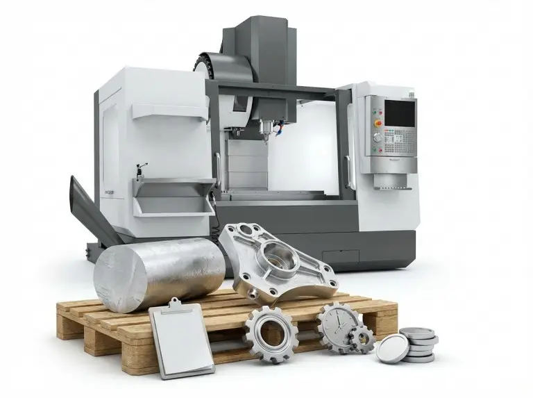

In most mechanical parts, simple flat surfaces are rare. Keyways, guide slots, T-slots, oil passages, and cooling grooves might look like simple ditches. But they often decide if a mechanism works smoothly. Slot milling is the main process for making these grooves reliably. It is also a very common method in modern CNC machining.
At Yonglihao Machinery, we have machined all kinds of slot-type parts. We serve industries like automotive, aerospace, electronics, and general machinery. For many clients, the main concern is not just “Can you mill this slot?” They want to know if it can meet design tolerances. They need it to assemble correctly, avoid vibration, and prevent early failure. They also want it to be cost-effective. In this article, we will explain slot milling. We will cover common processes, tool selection tips, and frequent issues. We will also show you how to design and order slots that are easier and cheaper to machine.
What Is Slot Milling?
In mechanical design and CNC machining, a slot is a long, narrow cavity. It can be open or closed. Its cross-section can be a rectangle, T-shape, semicircle, or dovetail. Slots may seem like just “grooves,” but they have key functions. They are used for keyed connections, guidance, positioning, and fluid passages. They also help reduce weight. If a slot is machined in the wrong place or has a poor surface, it can cause problems. It creates risks in assembly, vibration, and service life.
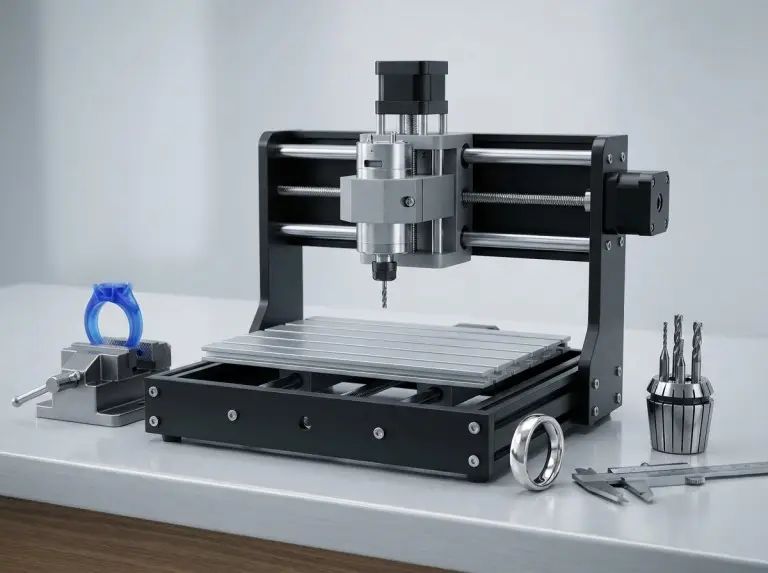
Slot milling uses a rotating milling cutter to cut a slot shape. The cutter, like a slot mill or an end mill, follows a set path on the workpiece. Compared to drilling, slot milling often requires the cutter to cut at its full width. Sometimes it cuts at more than its full width. This is especially true in deep, narrow slots. The process demands high rigidity from the tool and machine. It also requires good chip evacuation.
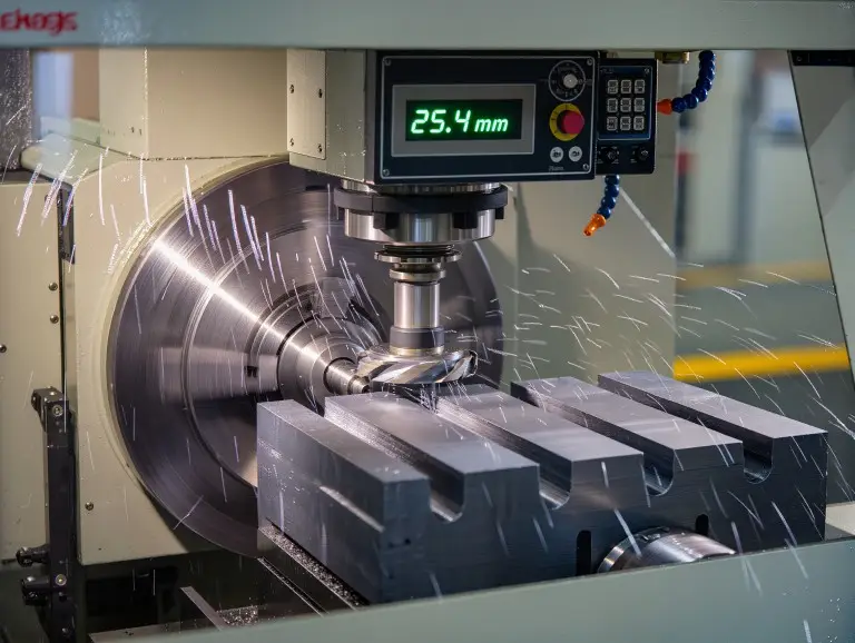
Modern CNC milling offers precise control over toolpaths, spindle speed, and feed rates. This allows slot milling to achieve tight tolerances. It can stably hold a slot-width tolerance of about ±0.02 mm. It can also produce a slot-bottom surface roughness of Ra 1.6 µm or better. This provides a solid geometric base for assembly, transmission, or sealing.
It is important to know the difference between a few concepts. People often use “slot milling” and “groove milling” for the same process. Both refer to milling slots or grooves in a part. Side milling uses the tool’s side edges to machine part surfaces or steps. It is sometimes used to widen or finish slot walls. Face milling uses a large face mill for big, flat surfaces. It is sometimes used to quickly cut shallow grooves on a large plane. Understanding these differences helps designers and engineers. It helps them decide if a slot needs only slot milling or a mix of processes.
The Role and Typical Applications of Slot Milling
From an application view, slot milling has three main roles. It transmits force and locates parts. It guides motion and fluids. It also optimizes weight and space. Because of this, it is used in almost all areas of precision CNC machining. Each industry, however, has slightly different priorities.
In the automotive and general machinery fields, slot milling is key. It is used for shaft keyways, locating slots, and oil passages. It also creates cooling slots on brake parts. The main focus here is on fit accuracy and fatigue life. In aerospace, slot milling machines light-weight pockets and connecting slots. It also creates cooling channels. These parts must reduce weight while keeping their stiffness and strength. In electronics and precision instruments, it is used for small slots on heat sinks and housings. These slots route wires, guide light, or mount sensors. Here, dimensional repeatability and surface quality are vital.
For machining companies, the value of slot milling is not just “being able to machine the slot.” It is about creating reusable process templates. These templates work with existing CNC equipment and tools. By reusing the same tools, toolpaths, and fixtures, we can reduce cycle time. We can also limit quality changes across different parts. This happens without buying more equipment. This is why at Yonglihao, we often help clients streamline and standardize processes. This ensures the same type of slot performs predictably across different parts and batches.
Common Slot Milling Process Types and Scenarios
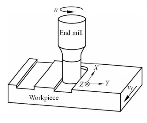
End Milling
Using an end mill for slot milling is the most common method. An end mill can plunge into the material with its end cutting edges. It can also feed along the slot direction with its side edges. This makes it great for machining straight slots, closed slots, and pockets. For rectangular slots of moderate width and depth, you can often form the slot in one pass. You just need to select a matching cutter diameter. For wider slots, you can use multiple parallel paths or trochoidal toolpaths to expand the width.
Note that when the slot depth nears three times the cutter diameter, issues can arise. The tool overhang increases and its rigidity drops. Using a “full-width single-pass” approach in these cases can cause tool deflection and vibration. A better method is step-down cutting. You can also split the job into trochoidal roughing and small-engagement finishing. This protects the tool and improves accuracy.
Side Milling / Side-and-Face Milling
When a slot is very long, deep, and has a simple shape, side milling is more efficient. This method uses a side-and-face cutter. These tools are usually mounted on a horizontal spindle or arbor. They have a thick core and high rigidity. Their cutting edges are spread around the circumference. This helps share cutting loads and improve chip removal. For long straight slots on guide rails or machine beds, side-and-face cutters often give better straightness and width consistency than a single end mill.
Of course, this process requires high rigidity from the machine and arbor. Tool mounting, cutter spacing adjustments, and insert replacement all need skilled technicians. For factories with horizontal milling machines, this is a key method for machining medium to large slots.
T-Slot Milling
T-slots are common on machine tool tables and fixtures. To machine them, you first use a standard end mill to cut the upper straight slot. Then, a special T-slot cutter is inserted into that slot. It expands the lower, wider part of the T-shape. The upper straight slot provides guidance and helps with chip removal. The lower “T-arm” holds clamping bolts or T-nuts.
In production, T-slots can have two common problems. First, the straight slot may not be wide enough. This causes poor chip evacuation when the T-slot cutter enters. The tool gets wrapped in chips. Second, setting the cut depth and feed too high for speed can cause issues. It can lead to tool shank bending or edge chipping. To fix this, you can widen the upper slot, cut in multiple passes, and use coolant or air to help remove chips.
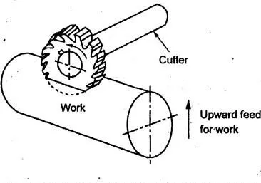
Woodruff Keyways
A Woodruff keyway has a semicircular cross-section. It matches a half-moon key and is used for torque transmission in shafts. Machining these slots requires special Woodruff key slot cutters. These cutters look like thin discs and come in different sizes for various slot widths and radii. The tool is usually mounted on a horizontal spindle and fed radially into the shaft to the right depth. Since cutting forces are focused, the tool’s quality, brazing, and heat treatment must be good. Adequate cooling is also necessary.
This type of keyway is very sensitive to size. If the slot is too wide, the key will wobble. If it is too narrow, the key will not fit. A misplaced slot will affect the angular position of gears or pulleys. We typically control the slot width within ±0.01–0.02 mm based on the client’s fit needs. We also perform a first-article check before mass production.
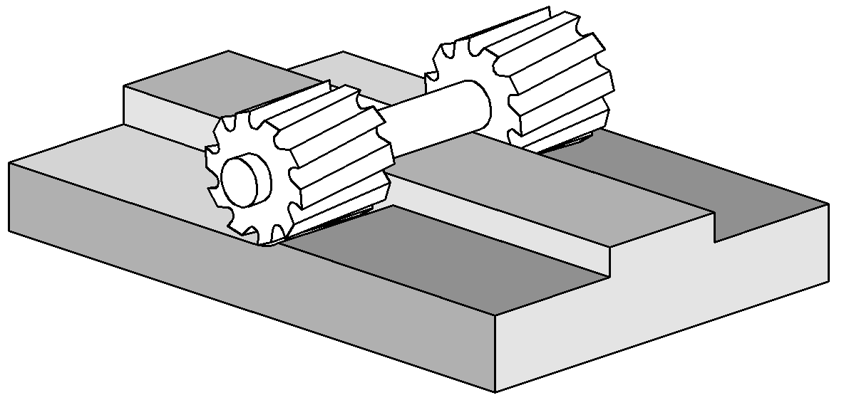
Gang Milling
Gang milling mounts several slot milling cutters on one arbor. This lets you machine multiple parallel slots or steps in a single pass. Common uses include multiple T-slots on a machine table or cooling slots on a heatsink. Compared to machining each slot one by one, gang milling can greatly shorten cycle time. It also improves the spacing consistency between slots.
However, gang milling has higher demands on equipment and process. The arbor, inserts, and machine must be rigid enough to handle the combined cutting forces. Adjusting the insert spacing also requires high precision. Once these conditions are met, gang milling is a very competitive option for batch production.
Common Slot-Milling Tools and Selection Keys
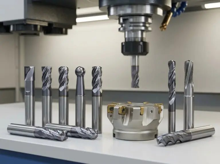
The slot milling methods above use different tool types. These include end mills, side mills, T-slot cutters, and Woodruff cutters. On the shop floor, the challenge is not finding the tool type. It is choosing the best specific tool for a particular slot.
When selecting tools, we look beyond the tool name. We consider the slot geometry, material, and machine rigidity. We focus on factors like:
- Slot dimensions: Width, depth, and whether it is closed determine the tool type and diameter.
- Material: The material (aluminum, steel, etc.) determines the tool substrate and coating.
- System rigidity: Machine and fixture rigidity limit the usable tool diameter and overhang.
- Requirements: Tolerances and surface roughness decide if separate finishing is needed.
A practical rule is to keep the slot width close to a standard tool diameter. Also, keep the slot depth within three times the tool diameter. This makes machining more stable. If you go beyond this range, you need better toolpath strategies. These include trochoidal milling or multiple depth steps to control deflection and chips. For keyways and guide slots with tight tolerances, we often use a “roughing tool + finishing tool” approach. This reduces the impact of tool wear on accuracy.
Typical Toolpath Strategies
The toolpath defines the “character” of slot milling. The same cutter can perform very differently with different toolpaths. The three common strategies are:
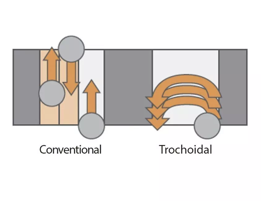
- Conventional Slotting: This involves feeding back and forth along the slot’s center line. It is simple to program and works well for shallow slots and general materials. The downside is that it creates high radial cutting forces and heat in deep slots or tough materials.
- Trochoidal Toolpath: The tool moves in a “circular-arc + forward” path. This controls the radial engagement in each loop. It reduces cutting force and improves chip removal. It is ideal for deep slots, narrow slots, and materials like stainless steel.
- Plunge Milling: This method uses mainly axial feed, like multi-point drilling. The tool then connects the holes into a slot with small lateral feeds. It is suited for very deep slots or when long-overhang tools are necessary, prioritizing safety.
In our projects, we prefer straight-line toolpaths for conventional slots. When the slot depth exceeds three times the cutter diameter, we switch. We use trochoidal roughing, followed by one or two straight-line finishing passes. When we have limited space and must use long tools, we use a plunge-type approach. This reduces the risk of tool breakage.
Process Optimization and Troubleshooting
Slot milling seems simple, but hidden issues can affect the yield. The problem is not cutting the material. It is controlling dimensions and surface quality. Here are some typical issues:
- Poor Entry Method: Direct vertical plunging can chip edges and raise burrs. It also leaves tool marks at the slot bottom. A better way is to use ramping or helical entry. This allows the tool to engage gradually. For closed slots, you can drill a pilot hole first. Then, you can expand the slot with a cutter at small radial engagement.
- Bad Chip Evacuation: Chips building up in deep, narrow slots cause problems. They lead to recutting, rapid wear, and even tool jamming. Solutions include step-down machining and reducing the cut depth per pass. Using coolant or high-pressure air to clear chips also helps.
- Low System Rigidity: Too much tool overhang or poor workpiece support causes issues. It leads to out-of-tolerance widths, wavy walls, and loud noise. To fix this, shorten the tool stick-out and add more workpiece support. You can also reduce feed, decrease radial engagement, or switch to a thicker toolholder.
For dimensions and surface quality, we separate roughing and finishing. Roughing focuses on removing material efficiently. Finishing uses smaller engagement, a smaller depth of cut, and more stable parameters. We may add a spring pass to fix errors from elastic deformation. This way, the slot dimensions and surface quality stay within the required range.
Advantages and Limitations of Slot Milling
From a process view, slot milling’s value is its flexibility. But it is not a solution for everything.
Main advantages:
- A common set of cutters can handle most slot types.
- It adapts well to different designs, good for small batches and frequent changes.
- It combines well with EDM and grinding. Milling removes bulk stock, and other processes finish critical surfaces.
Main limitations:
- Extremely deep and narrow slots are limited by tool rigidity and chip removal.
- The process window is very narrow for ultra-hard materials. It requires high-end tools and strict control.
- For parts sensitive to residual stress, grinding or EDM is often needed as a safeguard.
Therefore, we do not rely on slot milling alone. We let it handle most of the material removal. Then, we use other processes for areas needing high accuracy and surface quality. This helps balance cost and reliability.
Cost and Lead Time: Key Factors
From a project management view, slot milling cost is not linear. It depends on several key factors. Understanding these early helps avoid extra manufacturing costs.
The main variables affecting cost and lead time are:
- Slot Geometry: The width, depth, length, and shape of the slot matter.
- Tolerances: Tighter dimensions and higher surface needs increase finishing and inspection costs.
- Material Type: Aluminum and carbon steel are easy to cut. Stainless steel and high-temperature alloys are harder on tools and machines.
- Batch Size: Prototypes must cover all setup and programming costs. Mass production spreads these costs over many parts.
At Yonglihao, we assess the machining difficulty from drawings and 3D models. We then select a process route based on your batch size and lead time. If we find a design that does not match standard tools, we will suggest changes. This helps you find a good balance between function, cost, and delivery.
Conclusion
As a CNC machining service provider, Yonglihao Machinery does more than just mill your slots. We aim to provide a complete machining solution for slot-type structures. This includes offering advanced CNC milling services tailored to your needs. We have 3-axis, 4-axis, and 5-axis CNC milling centers. We also have turning, grinding, and wire-EDM equipment. This allows us to handle both single prototypes and mass production.
For size, we select cutters and processes based on slot width, depth, and material. We can achieve millimeter-scale widths and depths of tens of millimeters in steel and aluminum. For materials, we machine carbon steel, stainless steel, aluminum alloys, and more. We have developed mature libraries for each. In quality control, we measure key slot dimensions and positions. For keyways with high fit needs, we use gauges or CMM for verification.
If you have parts with slot structures, you are welcome to send us your drawings. We will provide a realistic slot-milling plan and quote. We will base it on material, batch size, and tolerance needs. If needed, we can suggest design adjustments to make the part easier to manufacture.
FAQ
How should I define slot width in my design for easy machining?
We recommend matching slot width to standard tool diameters (like 4, 6, 8, 10, or 12 mm) when possible. Odd dimensions (like 7.3 mm) require multiple passes or custom tools. This increases cost and risk. For features like keyways, you can adjust the key width or mating part to match a standard slot width.
What should I note for deep slots in design and process planning?
When slot depth exceeds three times the tool diameter, avoid very narrow widths. Widen the slot to help with chip removal. Also, note on the drawing that segmented machining is allowed. From a process side, we use step-down cutting and advanced roughing strategies. We then use finishing passes to refine the slot walls.
How should I indicate slot-related tolerances on drawings?
Clearly specify the slot-width tolerance, depth, and bottom shape. Also, note its distance from datum surfaces and its position relative to other features. If you need a specific surface roughness, mark the slot bottom and walls separately. This helps us plan our roughing and finishing strategies.
When is slot milling more suitable than EDM or broaching?
For slots with varied shapes, small to medium batch sizes, and good machinability, slot milling is the first choice. It is flexible and cost-effective. For extremely deep and narrow slots, sharp internal corners, or very hard materials, EDM or broaching has an advantage. Many complex parts use a mix of slot milling and other processes. We will recommend the best approach for your specific part.