
Milling operation selection for CNC parts works best when you tie each operation name to a specific feature, datum reference, and tool access constraint. Many quote and build problems happen when people treat “milling” as a single step instead of a feature-by-feature plan. This article explains milling operation types in a decision-first format. This supports RFQs, process planning, and prototype builds.
A milling operation describes how a rotating cutter engages material to make a defined surface or feature. Face milling creates broad planar faces. Slot milling creates narrow channels with chip evacuation constraints. These differences affect stability risks, burr behavior, and inspection strategies.
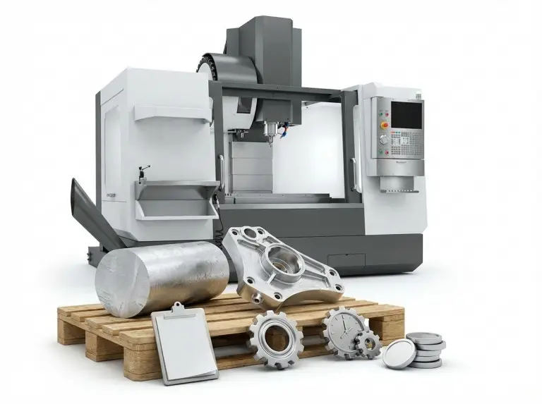
At Yonglihao Machinery, we use milling operation names as a shared language for CNC machining service reviews. We keep the language concrete. We link each operation to the feature outcome and the first condition you should verify. This approach reduces assumptions before programming and setup begins.
What is Milling Operations?
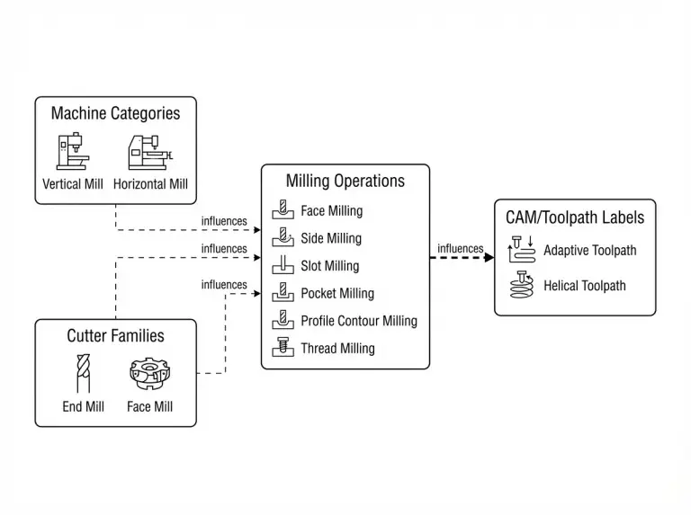
Milling operation is defined by cutter engagement and feature outcome. It is not defined by machine style, tool family, or CAM software labels. Operation types should describe the cutting action that produces a floor, wall, slot, thread, or profile. Machine categories and toolpath strategies affect feasibility, but they are not operation types.
Machine labels like vertical or horizontal mills describe a platform and typical spindle orientation. Tool labels like end mill or face mill describe cutter families with many geometries and limits. CAM labels describe how the toolpath is generated. This can matter operationally, but the label does not specify the feature outcome.
Two classification lenses keep terminology stable when parts get complex. The first lens is dominant cutter engagement. This separates face engagement, peripheral engagement, and mixed engagement. The second lens is feature geometry. This groups operations by planar faces, steps, walls, slots, pockets, profiles, threads, and gear teeth.
Milling Operations vs. Machine Categories
A milling operation name should answer which surface or feature is being produced. It should also say how the cutter engages to produce it. “Face milling a datum surface” is a verifiable operation statement because the outcome is clear and measurable. “Using a vertical mill” is not a milling operation because it does not describe the feature being created.
You must narrow tool family names to an operation statement before they become actionable. “End milling” can mean slot milling, pocket milling, profile contour milling, or finishing passes with different risks. A process plan should state the feature outcome first, then the tool family and strategy.
Classifying by Cutter Engagement and Geometry
Engagement-based classification helps predict stability and finish behavior. Face engagement usually depends on support under the cut and entry/exit conditions. Peripheral engagement depends on tool stiffness, wall height, and consistent engagement along the cut.
Feature-based classification keeps selection grounded in the drawing. A deep slot acts differently from a wide pocket, even if both are “internal features.” A thread or a gear tooth is a feature class with unique inspection and fit constraints. You should state these explicitly.
Common Misconceptions in Milling Selection
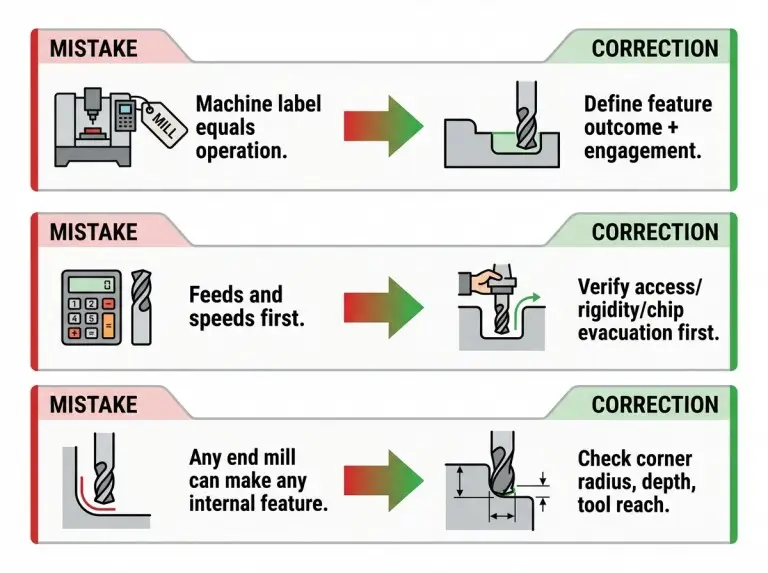
Most milling operation errors come from using labels as shortcuts. People often skip verifying geometry, access, and inspection intent. Readers memorize a list of operations and then apply the wrong one because they did not check feature constraints. The fastest improvement is to correct this habit, not to add more jargon.
Another recurring issue is treating parameter tables as the starting point. Speeds and feeds depend on material, cutter geometry, rigidity, coolant strategy, and chip evacuation. A stable plan starts with feature feasibility. It uses parameters as a controlled tuning step.
Confusing Machine Terms with Operation Types
Machine style terms hide the decision variables that actually control feasibility. A 3-axis CNC mill can perform face milling, pocket milling, and contour milling. However, it can still fail on a deep cavity due to tool reach and clamp interference. Operation selection should start from feature constraints. Only then should you validate against machine capability.
Terms like “universal milling” describe machine flexibility, not a specific cutting action. They do not tell an inspector what surface is being controlled or what geometry is being created. That gap usually leads to unclear acceptance criteria.
Verifying Feeds and Speeds Last
Feeds and speeds result from a verified setup and an engagement plan. Starting from a parameter table encourages false certainty. The real constraint is often tool overhang, wall compliance, or chip packing in a deep slot. Verification should focus first on reach, clearance, and support.
A stable milling plan should identify the dominant failure mode to prevent. Chatter, deflection, and burr formation typically trace back to rigidity and engagement conditions. You should control those conditions before numeric tuning begins.
CAM Labels Are Not Operation Types
CAM is a workflow for generating toolpaths. It is not a milling operation type that describes a feature outcome. A quote-friendly operation statement should specify the feature and engagement. For example, “pocket milling a cavity floor” or “thread milling an internal thread.” You can add the CAM strategy later as an implementation choice.
This distinction matters because CAM choices change cycle behavior and risk. However, they do not replace the feature requirement. If the feature is ambiguous, the CAM label does not resolve it. The process plan still needs geometry, datums, and inspection intent.
Main Types of Milling Operations
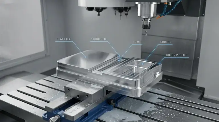
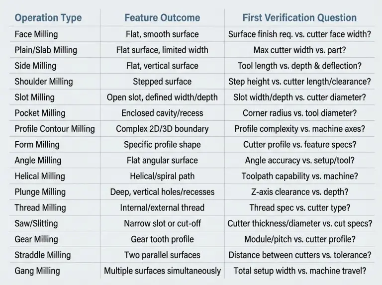
A practical list of milling operation types must link each operation to the feature it creates. It must also link to the first constraint you should verify. The goal is not to memorize names. The goal is to select an operation that matches geometry, access, and measurement. The short comparison table below highlights common confusions that appear in RFQs.
|
Commonly confused operations |
What differs in feature outcome |
What to verify before choosing |
|---|---|---|
|
Face milling vs plain milling |
Face milling targets broad planar faces with face engagement. Plain milling targets flat surfaces with peripheral engagement. |
Support under the cut, engagement consistency, and whether finish intent is functional or cosmetic. |
|
Side milling vs shoulder milling |
Side milling generates walls broadly. Shoulder milling targets a defined step with a crisp 90-degree shoulder. |
Step datum, shoulder height control, and tool stiffness for wall height. |
|
Slot milling vs saw slitting |
Slot milling targets channels with end mills or slot cutters. Saw milling targets thin slits and part separation behavior. |
Slot width, depth, chip exit path, and whether a thin kerf is required. |
|
Profile contour vs form milling |
Profile milling follows a path to generate shape. Form milling imprints a defined tool form into the part. |
Corner requirements, profile measurement method, and wear sensitivity of the formed geometry. |
|
Helical milling vs plunge milling |
Helical milling ramps to generate holes or cavities. Plunge milling removes material primarily axially. |
Machine rigidity, chip evacuation, feature depth, and clearance for ramp or plunge entry. |
Face Milling for Planar Surfacing
Select face milling when you must generate or clean a planar face with controlled flatness across a broad area. The primary verification question: Can you support the part under the cut without distortion or vibration? A robust plan states which face is the datum reference. It also explains how you will protect that datum during clamping.
Plain Milling for Flat Surfaces
Use plain milling to remove material and create flat surfaces where the cutter axis runs parallel to the workpiece. The primary verification question: Can engagement remain consistent along the cut length without causing taper from deflection? This operation often appears alongside slab milling terminology. The process plan should define the engagement and outcome, not just the name.
Side Milling for Walls
Side milling generates vertical walls, shoulders, and side faces using peripheral cutting edges. The primary verification question: Can wall height and tool overhang remain stiff enough to avoid wall bow or chatter? A reliable plan states whether a finish pass is required to control wall geometry.
Shoulder Milling for Steps
Shoulder milling targets a defined step with a flat floor and a vertical wall meeting at a crisp corner. The primary verification question: Which surfaces control the step and how will you measure the shoulder relative to datums? This operation needs explicit allowance planning when the shoulder is functional for assembly.
End Milling for Mixed Features
End milling describes a broad operation family used to create features through axial and radial engagement. The primary verification question: Which feature class is intended? End milling can mean slot, pocket, profile, or finishing work. A process plan should state the feature outcome and measurement intent rather than using “end milling” as a complete plan.
Slot Milling for Channels
Slot milling creates narrow channels where width is a controlling dimension. The primary verification question: Can chips exit the slot without packing, especially as depth increases? Inspection planning should also define how you measure slot width and position relative to the datum scheme.
Pocket Milling for Internal Cavities
Pocket milling creates internal cavities and generates pocket floors to a defined depth. The primary verification question: Do corner radii, depth, and tool clearance allow a stable tool reach without clamp interference? Treat pocket floors with functional sealing or bearing roles as controlled surfaces. They need explicit verification checkpoints.
Profile Contour Milling for Edges
Profile contour milling generates external shapes and controlled edge paths that define part size and fit. The primary verification question: Which edge is size-critical versus cosmetic? Finishing strategy and inspection focus differ for each. Fixturing must keep the part referenced to stable datums to prevent profile drift.
Form Milling for Defined Radii
Form milling uses a cutter with a defined profile to generate a matching contour on the workpiece. The primary verification question: Can profile tolerance and measurement method control tool wear effects? This operation makes sense when the geometry is consistent and inspectable as a formed feature.
Angle Milling for Chamfers
Angle milling generates features where the cutter engages at an angle to produce chamfers, grooves, or dovetail geometry. The primary verification question: Is the angle feature controlled by a datum? Is tool access available without collision? The process plan should state which angled surface is functional and how you will measure it.
Helical Milling for Circular Features
Helical milling generates holes or circular cavities by ramping a tool along a helical path. The primary verification question: Can the machine and setup maintain stable engagement during the ramp without chip evacuation failure? Select this method when controlled entry and circular interpolation behavior matter for feature quality.
Plunge Milling for Axial Removal
Plunge milling removes material primarily through axial entry. This helps in deep cavities or restricted lateral access. The primary verification question: Can the tool and setup manage axial load and chip evacuation without damaging feature walls? Frame this operation by access limits and stability risk, not as a generic roughing shortcut.
Thread Milling for Machinable Threads
Thread milling generates threads by moving a cutter along a helical path that defines thread geometry. The primary verification question: Are thread specification, feature access, and inspection method defined well enough to validate the thread? A process plan should confirm thread intent, such as fit expectations and verification approach. Do not assume a single “standard” outcome.
Saw Milling for Slitting
Saw milling, or slitting, uses a thin circular cutter to create narrow slits or separate sections. The primary verification question: Are a thin kerf and controlled cut path required? Does the setup prevent part vibration during separation? This operation is sensitive to workholding and part deformation when sections become thin.
Gear Milling for Teeth Profiles
Gear milling generates gear teeth using cutters and toolpaths designed for tooth geometry. The primary verification question: Which tooth geometry and measurement method define acceptance for the application? Because gear features are functional and inspection-driven, the RFQ should state how you verify the gear. It should also state what constraints matter most.
Straddle Milling Parallel Faces
Straddle milling machines two parallel faces simultaneously. This reduces setups when spacing and parallelism matter. The primary verification question: Can alignment and datum scheme control both faces reliably in one setup? Inspection planning should separate spacing control from parallelism control to diagnose drift.
Gang Milling Multiple Features
Gang milling mounts multiple cutters to produce several features in one pass. The primary verification question: Are feature tolerances compatible with shared alignment and runout effects across cutters? This approach works best when repeatability and handling reduction outweigh the added alignment verification steps.
Criteria for Selecting Milling Operations
Operation selection becomes defensible when you verify geometry, datums, and inspection targets before choosing tools or parameters. Readers should treat selection as a constraint check, not a preference statement. The correct operation is the one you can execute and measure under access and rigidity limits.
Geometry drives tool diameter and reach, which drives deflection risk. Datums drive how errors stack and how you verify features. Requirements drive whether you need a rough and finish sequence. They also determine which surfaces deserve controlled finishing.
Feature-Driven Selection
Feature classification should start with the surfaces that control function. A sealing face and a cosmetic face can both be flat. However, the verification priority and finishing approach differ. A thread or gear tooth is a feature class you should name explicitly because acceptance is inspection-driven.
Operation selection should identify the controlling surface for each feature. Slot milling typically controls channel width. Pocket milling typically controls floor depth and cavity clearance. Thread milling and gear milling require definition of how you verify the feature. Geometry alone may not describe functional acceptance.
Datum Logic and Feasibility
Datum strategy determines where the workpiece is referenced and where tolerances are anchored. Face milling often creates a stable datum plane early. Later walls and profiles reference this plane. A weak datum plan can produce consistent parts that still fail assembly because the reference stack was wrong.
Setup feasibility depends on workholding and access. A deep pocket may be machinable in theory. But it might be impossible in practice if clamps block tool entry or force excessive overhang. A credible plan should state clamp zones, clearance assumptions, and the inspection faces used to validate setup stability.
Tolerance and Surface Intent
Tolerance intent affects whether you produce a feature in one operation or split it into rough and finish passes. Walls that control fit often benefit from finishing strategies that control deflection and leave consistent allowance. Floors that control assembly height often require stable finishing conditions to avoid chatter patterns.
Surface intent also changes risk management. Burr behavior and edge quality depend on material and tool exit conditions. Direction choices and finishing sequence influence these conditions. Those decisions should be framed as verification choices that depend on machine behavior and setup stiffness.
Stability and Risk Trade-Offs
Stability, chip control, and access limits drive trade-offs across milling operations more than the operation name itself. Chatter and deflection correlate with tool overhang, wall compliance, and engagement mode. A reliable plan identifies the dominant risk and selects an operation that reduces that risk.
Different operations create different chip evacuation demands. Slot milling and deep pocket milling concentrate chips in confined spaces. Face milling typically disperses chips more freely. These differences affect heat, burr behavior, and whether a feature can be produced without secondary cleanup risk.
Engagement and Rigidity Limits
Rigidity limits depend on the complete system. This includes spindle, toolholder, cutter, and workpiece clamping. Long reach tools amplify deflection. This can change wall straightness or floor flatness. A stable plan minimizes overhang and avoids unnecessary engagement severity for the feature.
Interrupted engagement and thin-wall sections increase vibration risk. Peripheral and side engagement can become unstable when the part provides limited support near the cutting zone. Verification should focus on support placement and whether feature geometry turns the part into a compliant spring.
Managing Chip Evacuation and Burrs
Chip evacuation risk is highest in deep slots and pockets with restricted exit paths. Chip packing can cause re-cutting, heat, and edge damage. This shows up as poor surface or dimensional drift. The operation plan should define the chip exit path and whether coolant or air assistance is feasible.
Burr risk depends on material behavior and cutter exit direction at edges. Direction choices such as climb or conventional milling can change how the cutter loads the part. They also change how edges break. The appropriate choice depends on machine backlash control, workholding stiffness, and edge-quality requirements. Treat it as a verifiable decision.
Tool Reach and Corner Constraints
Reach constraints appear when feature depth requires long tools or when fixtures block access. A small internal corner radius can force a small-diameter tool with increased deflection risk. The process plan should state the minimum acceptable internal radius. That single constraint can reshape the entire operation route.
Corner and access constraints also affect finishing behavior on profiles. Tight radii can change engagement and create local surface differences. Verification should identify which corners are functional and how you will inspect them.
Conclusion
Reliable milling operation selection comes from matching types to feature geometry, datum intent, and verified tool access. At Yonglihao Machinery, we treat the operation list as a decision tool for our milling services, not a vocabulary list. We review drawings for corner radii, reach limits, and inspection priorities before locking a process route. When a requirement depends on setup rigidity or chip evacuation, we state the dependency. We verify it with the intended clamping and measurement method. Share critical datums, functional surfaces, and accessibility constraints early. We can then align operation choice with the outcomes the part must achieve.
FAQ
Practical milling operation decisions depend on feature constraints. You should state and verify these before programming starts. The questions below focus on the most common selection forks that change operation choice and inspection risk.
When to use face milling vs. plain milling?
Face milling is usually safer when you must generate a broad datum face with predictable planar surfacing. Plain milling fits when peripheral engagement along a long surface is the dominant condition and setup keeps engagement consistent. Verify the choice against part support, interruption risk, and which face controls downstream datums.
When is slot milling better than saw slitting?
Slot milling is typically right when a channel is a functional feature with controlled width, depth, and position. Saw slitting is right when you need a thin kerf, a narrow slit, or part separation behavior. Verify the decision against chip exit path, workholding stability as sections thin, and required slot geometry.
Should I use thread milling or tapping?
Thread milling is often preferred when you can maintain controlled thread generation and access clearance with a helical toolpath. Tapping works when access, thread specification, and risk tolerance align with an axial forming or cutting method. The best choice depends on accessibility, material behavior, and how you verify thread acceptance.
When to choose helical vs. plunge milling?
Helical milling is usually better when controlled ramp entry and circular feature quality are priorities for holes. Plunge milling helps when lateral access is constrained and axial removal fits rigidity conditions. The correct choice depends on machine stiffness, feature depth, and whether chip evacuation remains reliable.
What to define for gear milling quotes?
Do not quote gear milling work without defined tooth geometry intent. You also need a measurement approach that matches functional acceptance. Gear features are inspection-driven. A generic “gear milling” label does not specify what must be controlled. Inputs depend on mating conditions, inspection method, and which surfaces are function-critical.
When are straddle or gang milling useful?
Consider straddle or gang milling when multiple faces or features share a datum scheme. It is also worth it when handling reduction has measurable value. These approaches increase alignment and stack-up risk. They require spacing verification and a clear inspection strategy. If features carry different tolerance priorities, separate operations can be easier to control.