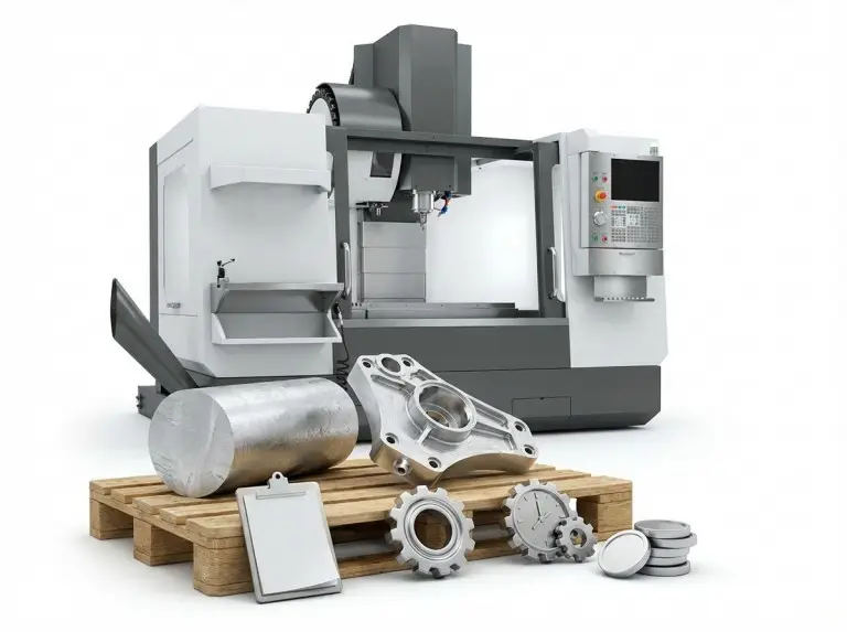


CNC machining is very flexible. However, every part has physical size limits. These are set by the work envelope, axis travel, and how small tools and features can be.
If you understand these limits early, you can design better parts. Your parts will fit available machines and hold the right tolerances. This avoids costly rework or redesigns. This article covers size limits for engineers. It looks at part envelope, process limits, and minimum feature sizes. It also explains what to change in your design when you approach these limits.
How Part Size Affects CNC Machining Outcomes
Part size affects which machines you can use. It also impacts how rigidly you can hold the workpiece. This makes it harder to control tolerances. A small part that fits well inside the work envelope is easy to fixture. It is simple to reach and finish in one or two setups.
As a part gets longer, wider, or taller, fixturing becomes harder. You often need extra setups. This increases variation and cost. Very small parts cause a different problem. You enter the world of micro-machining. Here, tiny tools and low rigidity make the process much tougher.
General Size Constraints
To understand the real dimensional capability of a CNC machine, you mainly need to look at three constraints: the work envelope, X/Y/Z axis travel, and the effective tool reach.
CNC Work Envelope and Machine Footprint
The CNC work envelope is the 3D space a machine can cut. It sets the maximum part size for a single setup. For a mill, this is its X, Y, and Z travel. For a lathe, it is the swing and the distance between centers.
You also need space for fixtures, clamps, and safe tool movement. A part might technically fit by its dimensions. But if there is no room for fixtures or tool paths, it is still too big in practice.
Axis Travel (X/Y/Z) and Maximum Part Dimensions
Axis travel is the linear movement of each axis. It numerically defines the work envelope. The X and Y travel limit the part’s maximum length and width. The Z travel limits its usable height after you account for fixture thickness and tool length.
If a part is larger than any axis travel, you have two options. You can split the design into smaller pieces. Or you can machine it in multiple setups. Each extra setup adds alignment risk. It also makes it harder to hold tight tolerances, like ±0.01 mm on long features.
Tool Reach, Tool Holder Clearance, and Z-Direction Limits
Tool reach is how deep a cutter can go while staying accurate and clear of collisions. Even with large Z-axis travel, the tool often limits the effective depth. Tool length, holder size, and nearby geometry are the main factors.
A common rule is to keep milling depth within 3–4 times the cutter’s diameter. This ensures stable cutting. Longer tools are possible, but they increase chatter, deflection, and cost. You should only use them when absolutely necessary.
Process-Specific Size Limits: Milling, Turning, and Drilling
For the same part geometry, milling, turning, and drilling have very different workable size ranges and limits, so it is important to understand the typical capacity boundaries of each CNC process separately.
CNC Milling
In milling, table size and axis travel limit the part envelope. This is the largest part you can fixture and machine in one setup. The part and its fixture must fit on the table. They must also be under the machine’s weight limit.
Deep pockets and tall walls are often limited by tool reach and rigidity, not the machine itself. Wide, shallow parts are easier to handle. Narrow, deep housings can cause stability and surface quality problems if the design isn’t adjusted.
CNC Turning
For turning, the distance between centers defines the maximum length of a shaft. It must be supported between the spindle and tailstock. If the part is longer, you need a bigger machine or a design change.When planning your project, using a CNC turning online quote tool can help you quickly evaluate the feasibility and cost of machining your part within these constraints.
Swing over bed and swing over cross slide define the maximum diameter. This is the largest diameter that can rotate and still be reached by the tool. The usable diameter is a bit less than these values to ensure clearance. Large flanges or discs might be limited by their diameter even if they are short.
CNC Drilling
In drilling, the work envelope limits the overall part size. Drill length and stiffness limit the hole depth. A safe limit is about 10 times the drill diameter. Beyond that, chip removal and deflection become major problems.
The minimum hole diameter depends on the smallest reliable drill. When holes are in the micro-drilling range, other factors become critical. These include spindle runout, coolant delivery, and material consistency. Cycle times also increase a lot.
Minimum Feature Size, Wall Thickness, and Cavity Depth
Common design questions like “is this too small, too thin, or too deep” essentially come down to whether minimum feature size, minimum wall thickness, and cavity depth stay within a stable engineering range.
Minimum Feature Size and Micro-Machining Considerations
Minimum feature size is set by tool diameter, machine precision, and fixture stability. Very narrow slots, thin ribs, or tiny steps need small cutters. These cutters are less rigid and more sensitive to tool runout.
When a feature’s size gets close to the tool’s diameter, you are in micro-machining territory. At this point, small changes in setup or material can cause large errors. It is better to keep feature sizes well above the theoretical minimum unless the part’s function requires it.
Thin Walls
Thin walls are limited by how much they bend under cutting forces. If a wall bends during machining, it springs back afterward. This causes dimensions to shift, even with a perfect toolpath.
The practical minimum wall thickness depends on material stiffness and wall height. Short aluminum walls can be thinner than tall steel walls. But any wall with a high aspect ratio is risky. Adding ribs, shortening unsupported height, or thickening key areas can help you stay within safe limits.
Deep Cavities and Holes
Depth limits come from the ratio of feature depth to tool diameter. A very deep, narrow cavity acts like a long tube. It magnifies every vibration and makes chip removal hard.
For milling, going deeper than a few tool diameters requires special tactics. This might include step-down passes or using long tools just for finishing. For drilling, very deep holes often need peck cycles or through-tool coolant. You might also need to change the design to allow for larger diameters or shorter depths.
Design Guidelines Within CNC Size Limitations
There is a clear gap between what is theoretically machinable on paper and what is robust and economical on the shop floor, and closing this gap requires targeted design optimizations in part splitting, fixturing orientation, and the allocation of tolerances and structural detail.
Splitting Oversized Parts and Planning Joints
When a part is too big for available machines, splitting it is often best. Each smaller piece can be made to fit a standard machine and fixture.
Place joints where tolerances are easier to hold. Use assembly features like locating pins or shoulders. This reduces the risk of stacked errors and keeps you within realistic size limits.
Orienting Parts and Using Multi-Axis Machining to Improve Access
Smart part orientation can make a difficult job much easier. Rotating the model in the fixture can reduce its X or Y dimensions. It can also expose features so you can reach them with shorter tools.
4-axis and 5-axis machines improve this by adding rotational axes. They let you machine multiple faces without re-clamping the part. This gives you better access within the same work envelope and reduces the number of setups.
Adjusting Tolerances and Features to Match Machine Capability
Size and tolerance are linked. It is easier to hold ±0.01 mm on a small feature near a fixture. It is much harder on a long feature that spans most of the axis travel. There, issues like straightness, thermal expansion, and tool deflection add up.
During design, use tight tolerances only where they are truly needed. Use general tolerances, like ISO 2768, for everything else. Simplifying small details and relaxing tolerances on large spans can bring a design back into a stable, cost-effective process.
Quick Design Checklist for Size Limitations:
- Does the part and fixture fit inside the machine’s work envelope and weight limit?
- Are deep pockets and holes within sensible depth-to-diameter ratios?
- Are minimum feature sizes compatible with standard tool diameters?
- Are thin walls stiff enough for the material and wall height?
How Size Limitations Influence Cost and Machine Selection
Part envelope and feature scale not only decide whether a part can be machined on a given CNC, but also drive machine class selection, fixturing complexity, and unit cost, so they must be evaluated early in process planning and quoting.
Matching Part Envelope to Machine Class (Small/Medium/Large)
Part size often decides if you need a small, medium, or large CNC machine. Smaller machines usually have lower hourly rates. They are also cheaper to set up. Keeping the part small often reduces cost.
If a design requires very large gantry mills or heavy-duty lathes, expect higher costs. This is true even if you don’t use all the extra capacity. These machines have more complex fixturing needs.
Impact of Oversized Parts on Setups, Fixturing, and Repositioning
Parts that are near the limits of axis travel or table size need special fixtures. They also require multiple clamping positions. Every extra setup adds time and increases the chance of small misalignments.
Heavy parts also need careful control of table load and weight distribution. Ignoring the machine’s weight capacity can hurt accuracy and shorten the machine’s life, even if the part technically fits.
Trade-Off Between Tight Tolerances, Size, and Machining Time
Large parts with tight tolerances are the hardest to machine. Holding small tolerances over long distances needs slower feeds and lighter cuts. Machinists may need more tool paths and more inspection. All of this increases cycle time.
If possible, widening tolerances on large features can greatly reduce machining time and scrap. Talk about these trade-offs with your machining partner early. It is the fastest way to balance function and cost.
Conclusion
Size limits in CNC machining are more than just table dimensions. They are a mix of work envelope, axis travel, tool reach, and minimum feature size. They also include wall thickness and realistic tolerance levels. Designing with these limits in mind makes machining more predictable and cost-effective. It also greatly reduces the risk of late-stage redesigns.
At Yonglihao Machinery, we check each project carefully. We map the part’s geometry against our equipment’s real abilities. We check the work envelope, distance between centers, swing over bed, tool reach, and fixturing options. We do this before we decide on a process and fixture design. This approach helps us stay within practical size limits. It also lets us deliver stable quality and lead times. If you are checking if a part is right for CNC machining, review these size boundaries early with your machining partner. It is the fastest way to avoid rework, control costs, and ensure the design is manufacturable.
FAQ
How big can a CNC-machined part realistically be?
A part can be as large as the work envelope and weight capacity allow, with extra room for fixtures and tool access. When a part uses most of the axis travel or weight limit, managing setups and costs becomes very hard. Splitting large designs into smaller parts is often more reliable than making one huge piece.
How small can features be before they require micro-machining?
Features enter the micro-machining range when their size is close to the smallest tool your supplier can run. At that point, tool breakage and material issues control the process. When you can, design narrow slots and small holes to match standard tool diameters instead of the absolute minimum.
What is a practical minimum wall thickness for CNC machining?
A practical minimum wall thickness is one that can handle cutting forces without bending too much. It depends on the material and wall height. Short aluminum walls can be thinner than tall steel walls, but any wall with a high aspect ratio is risky. If you need very thin walls, consider adding ribs or redesigning the part so the wall is supported during machining.
How deep can holes and cavities be machined accurately?
Holes and cavities are usually limited by depth-to-diameter ratios, not just Z travel. For drilling, depths around 10 times the hole diameter are a common upper limit. For milling, stable pocket depth is usually much less. Deeper features may need special tools, peck cycles, or design changes to increase diameters or shorten depths.
How do 3-axis, 4-axis, and 5-axis machines change size limitations?
Multi-axis machines do not change the physical work envelope, but they use it better by improving access. A 4-axis or 5-axis machine can rotate and tilt the part. This allows shorter, stiffer tools to reach multiple faces and complex shapes. This reduces setups, improves accuracy, and expands what is possible within the same machine size.