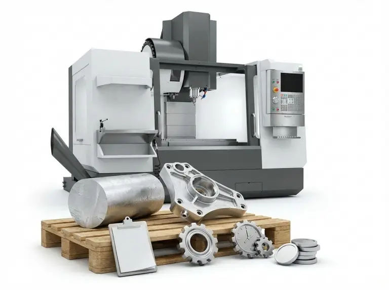

Precision gear cutting works well. It matches tooth shape, process steps, and checks to your load, speed, and noise goals. At Yonglihao Machinery, we produce cnc machining parts from prototypes to production.
This article covers gear cutting in CNC. It includes main cutting and finishing steps. It lists common gear types we machine. It gives a simple selection workflow. The focus is on CNC gear cutting. It includes related hard-finishing steps. These achieve steady meshing and long life.
Gear Cutting in CNC Machining
Gear cutting removes material from a blank. It creates exact tooth spaces. Gears mesh smoothly. They transfer torque with low noise and wear. In our shop, precision means tooth profile, pitch steadiness, runout, and finish work together. They cut vibration. They prevent early failure under your conditions.
Most gear teeth follow a set shape. They do not rely on what the cutter leaves. That shape sets contact pattern and load spread. It affects efficiency. It shows how the set handles alignment errors in assembly.
Tooth Profile: Involute vs. Cycloidal
Involute teeth are common. They handle small center-distance errors. They keep good meshing. Cycloidal profiles appear in specific mechanisms. They show in old designs. They help in certain contact conditions. But they need tight control of mating shape and checks.
From machining, the key is not the curve name. It is if the drawing defines the profile clearly. It is how to verify it. If checks are vague, you risk passing sizes. But you still get noise or uneven wear.

Pressure Angle (14.5° / 20° / 25°)
Pressure angle drives tooth strength and behavior. We see it as design intent, not default. Higher angle makes stronger teeth. It raises load capacity. But it can boost noise and vibration if the system lacks design for it.
A 20° pressure angle is common. It balances strength and efficiency in many industrial uses. If your application has tight noise limits or odd loading, we check the angle early. It affects tooling choices, cutter shape, and acceptance rules.

Pitch and tooth spacing
Pitch spaces the teeth. Pitch steadiness makes a gear run smooth. It avoids “mostly work.” Even if a tooth looks right, poor spacing causes issues. Indexing error or high runout creates load changes. These show as vibration, heat, and fast wear.
Pitch needs are where CNC setup matters most. Workholding stability is key. Rotary axis calibration is key. Blank reference decides if the gear acts precise or noisy.

Main Gear Cutting Processes
No single best gear cutting method exists. The right one depends on teeth type. It depends on batch size. It depends on needed accuracy. It depends on heat treatment. Below are main processes we use in CNC. We explain what each delivers best.
Gear hobbing
Gear hobbing is common for external spur and helical gears. It is fast and repeatable in production. A rotating hob and blank move in sync. This makes tooth creation continuous and efficient.
Hobbing skips internal gears due to tool access. For internal teeth, we use shaping or broaching. We base it on volume and shape limits.

Gear shaping
Gear shaping uses a back-and-forth cutter. It mirrors the tooth space. Cutter and blank rotate together. This method helps for internal gears. It helps for features near shoulders or blocks where tools cannot reach.
Shaping can be slower than fast continuous processes. The return stroke slows it. But it stays reliable for complex shapes and small-to-medium batches. If your design has tight spaces or risks, shaping is often safest for good tooth shape.

Gear milling
Gear milling cuts one tooth space at a time. It uses a form cutter or milling plan. It indexes the blank between cuts. It suits prototypes and low-volume work. It suits very large gears where hobs are impractical. Tool cost is hard to justify there.
Milling helps when you need custom work without special gear tools. The tradeoff is time. Tooth-by-tooth work is slower than continuous for production.
Gear broaching
Gear broaching pushes or pulls a multi-tooth broach through a bore. It creates internal splines or gear profiles in one pass. It is fast and consistent with a dedicated broach. Production volume must support tooling cost.
The limit is cost and flexibility. Broaches tie to specific profile and size. For custom low-volume internal gears, broaching is rarely economical.
Gear grinding
Gear grinding finishes tooth surfaces with an abrasive wheel. It follows heat treatment often. Use it for very tight tolerances. Use it for better finish and less noise. It fits high-speed applications.
Grinding takes more time. It needs special equipment. Reserve it for high-performance needs, not general gearing. If heat treatment is planned, we discuss grinding. It corrects distortion and meets final rules.

Gear finishing (honing/lapping/burnishing)
Finishing methods like honing, lapping, and burnishing improve surface texture. They improve contact behavior. They do not remove large errors. These steps cut noise. They boost meshing by removing tiny flaws from earlier cuts.
Finishing does not replace correct shape. But it works as a final step when form and spacing meet targets. We match finishing to your noise, life, and lubrication goals. We avoid generic polish.
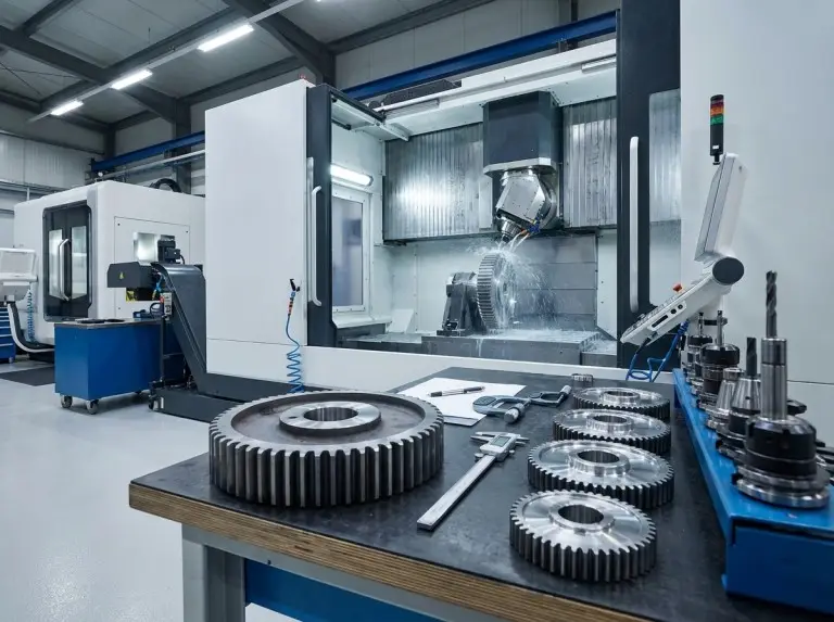
Main Types of Gears We Machine
Gear type selection matches performance needs to space limits. The same ratio can use different ways. These give varied efficiency and noise. We machine common types with CNC. We review each with typical use. We note manufacturing effects on consistency.

Worm gear
Worm gearing gives high reduction ratios. It fits compact setups. It can self-lock in some setups. Choose it for tight packaging. Choose it for large speed reduction in one stage.
The tradeoff is efficiency. Sliding contact makes more heat and losses than other types. Material pairing matters. Surface quality matters, especially for wear life vs. friction.
Bevel gear
Bevel gears send power between crossing shafts. They appear in drivetrains and angle gearboxes. They fit systems that turn power through an angle. Variants like straight, spiral, and hypoid handle load, noise, and smoothness.
Bevel shapes can be sensitive to setup and checks. We confirm the variant and contact needs early. Bevel gear is a family, not one standard tooth form.
Spur gear
Spur gears are straightforward. Teeth run parallel to the axis. They work efficiently for parallel shafts. They are cost-effective and strong when noise is not key.
Their limit is noise at higher speeds vs. helical. If your system is speed-sensitive or has strict sound targets, spur gears may work. But they need careful tooth accuracy and alignment.
Helical gear
Helical gears have angled teeth. This creates gradual engagement. It runs smoother than spur gears. Use them for higher load and lower noise.
Consider axial thrust. Bearings must support it. Account for it in assembly. We note this early. The gear may seem like a simple swap. But system loads differ.
Herringbone gear
Herringbone gears combine opposite helix angles. They cancel axial thrust. They keep smooth meshing. Use them in tough applications for high load and stable work.
They are complex and costly to make. We see them when performance beats manufacturing effort. If you need quieter than spur, helical is often simpler.
How We Choose Gear Type and Cutting Method?
Choose gear type and process together for stable, low-cost gears. In practice, we start with your targets. We turn them into gear needs. Then we pick a method that hits them steady at your volume.
We use three axes: geometry access, production volume, and precision needs. Materials and post-steps align to that.
What we ask you to confirm before we lock the route (one checklist):
- Gear type and whether teeth are external or internal, plus any shoulder/interference constraints.
- Load, speed ratio, noise limits, and environment (lubrication, temperature, contamination).
- Pressure angle, pitch definition, and any special tooth profile requirements, plus how you plan to inspect/accept the gear.
This framework prevents over-processing. If your gear is a prototype for fit and basic function, milling plus careful inspection may be ideal. Grinding could add needless cost. If your application is high-speed and noise-sensitive, skipping hard finishing can cause whine and issues. This happens even if the gear meets basic dimensions.
Production Workflow, Tooling, and Quality Control Checkpoints
Reliable gear cutting controls references and checks. It is not just running a program. Our workflow keeps the blank stable. It keeps indexing consistent. It manages heat and tool wear. It verifies parameters that predict meshing behavior.
Blank preparation and workholding to control runout
A good gear starts with a good blank. Tooth accuracy cannot fix unstable shape. We confirm blank dimensions and material condition. We check reference features like center holes or mounting faces. These drive runout and pitch steadiness after cutting.
Workholding minimizes runout and bend under forces. Small motion at the blank becomes error at the tooth. If the gear assembles on a shaft or hub, we align references with functional datums. This avoids perfect teeth on the wrong axis.
Machine setup and the tooling that makes the process repeatable
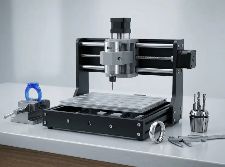
Core equipment depends on the process. The goal is consistent indexing and alignment. CNC milling centers handle prototypes and custom work. Dedicated machines like hobbers or shapers fit production or internal gears.
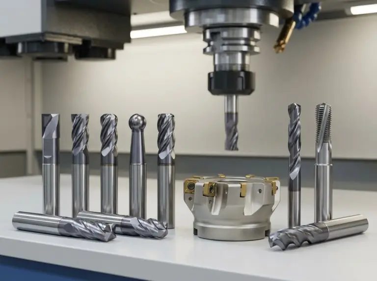
Tooling follows tooth shape and process. Hobs, shaper cutters, form cutters, broaches, and grinding wheels each play a role. We treat the dividing head or rotary table as precise. Accurate rotation and indexing are key to tooth spacing.
Programming levers: feeds, speeds, toolpaths, and coolant
Programming balances surface quality, tool life, and time. It protects tooth shape. Feed rates and cutting speeds get tuned to material and tool. Depth of cut and paths also get tuned. Aggressive settings increase wear and heat. Conservative ones raise cost. They can leave poor surfaces.
Cooling and lubrication are key in gear cutting. Thermal growth affects fit and wear. Heat-affected layers do too. We plan coolant around material, tool coating, and chip load. This keeps tooth form stable.
Post-processing: deburring, heat treatment, and finishing steps
Post-processing decides if gears succeed or fail. It handles burrs and edges that affect assembly and wear. Deburring removes sharp edges. It avoids damage to tooth form. Uncontrolled deburring can round the tooth. It changes contact.
If heat treatment is planned, we prepare for distortion. We plan hard finishing to meet final tolerance. Finishing like grinding, honing, or lapping fits surface and noise goals. We avoid generic add-ons.
Inspection points that predict real meshing behavior
Quality control verifies meshing features. These are tooth profile, pitch accuracy, runout, and finish. We use metrology for the need and volume. We document results for repeatability and traceability.
Inspection improves process control. Gear cutting reacts to tool condition and alignment. When issues show, we check tool wear. We check machine calibration. We check workholding stability. We check cutting parameters that influence deviation.
Conclusion
Precision gear cutting is reliable. Align three things from the start. Match the gear type to your application. Pick the cutting method that holds accuracy at your volume. Use the inspection plan that proves meshing. CNC makes this possible. But it needs clear inputs like pressure angle, pitch, and post-processing.
At Yonglihao Machinery, we handle CNC gear cutting for prototype manufacturing and batches. We pair process selection with setup and QC checks. Share your drawing, volume, material, and constraints. We recommend a route and checks. This delivers trusted gears in assembly. Not just parts that look right on paper.
FAQ
What is the most common method used for precision gear cutting?
Hobbing is the most common for external gears. It is fast and repeatable for spur and helical designs. It works best for moderate to high volume. The gear must be external with good hob access. For internal teeth, use shaping or broaching.
How do I determine the correct pressure angle for my gear application?
The correct pressure angle meets strength and noise needs. It matches the mating set and constraints. A 20° angle is common. It balances tooth strength and efficiency for industrial uses. Higher angles strengthen teeth. But they may raise noise and vibration at speed.
What is the role of a dividing head or rotary table in gear cutting?
A dividing head or rotary table gives accurate indexing. Each tooth space positions right relative to the last. Indexing accuracy ties to pitch consistency and smooth meshing. Unstable indexing lets the gear meet basic dimensions. But it runs noisy.
Can CNC machining cut gears with complex or custom tooth profiles?
Yes. CNC can make complex or custom profiles. The geometry must be clear. The process must support verification. Milling strategies are flexible for prototypes and special forms. They skip dedicated tooling. The limit is often checks and tolerance, not shape creation.
What are the key factors to consider when selecting a gear type?
Key factors are load and speed ratio. They include space constraints and noise limits. They include efficiency and environment. These set if spur, helical, herringbone, worm, or bevel fits best. Consider manufacturability. Consider post-processing for targets.
How does pitch affect gear performance?
Pitch consistency affects engagement, vibration, and wear. Inconsistent spacing creates cyclic loading. It shows as noise, heat, and early damage. Setup, indexing control, and runout management are central to precision gear cutting.