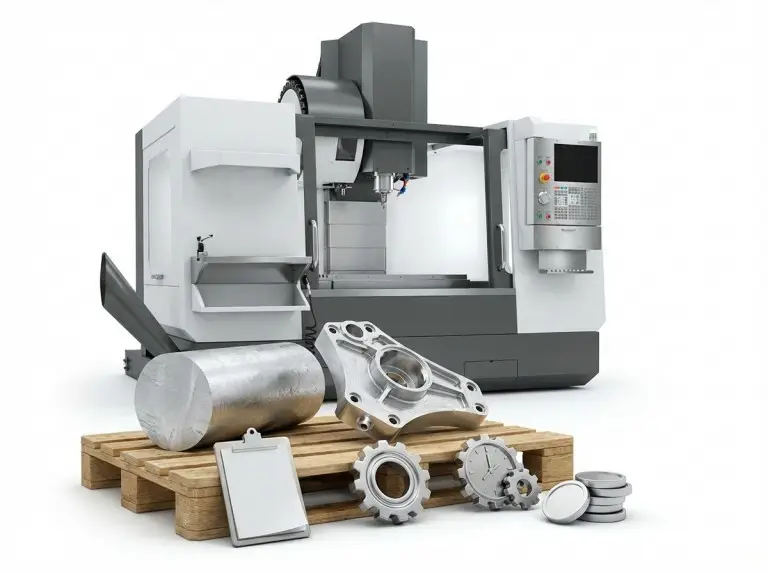

A CNC milling spindle is the core component that turns programmed commands into stable cutting. It directly impacts surface finish and geometric accuracy in milling. We prioritize spindle checks during quoting and planning for CNC machining services because many finish and tool-life problems start with the spindle system, not the toolpath..This guide covers spindle boundaries, common types, and verification steps that lower risk in both prototype manufacturing and production milling.
Spindle selection often fails when shops use a high-RPM spindle for a high-torque job. It also fails when a torque-focused spindle is pushed into high-speed finishing without proper system support. We will separate the decision factors so you can match the right spindle to your milling load, tool diameter, and duty cycle. We will also translate maintenance topics into actions that prevent bearing damage and unplanned downtime.
What is CNC Milling Spindle?
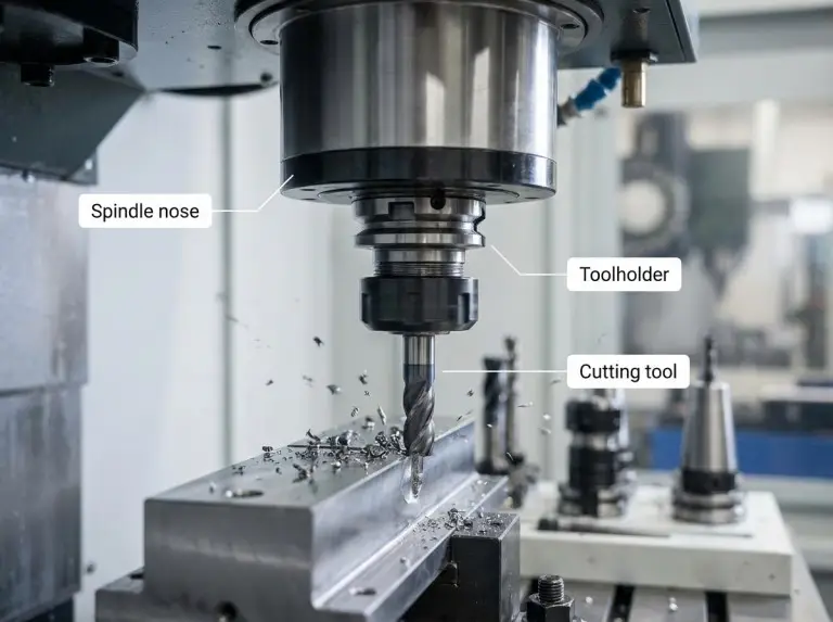
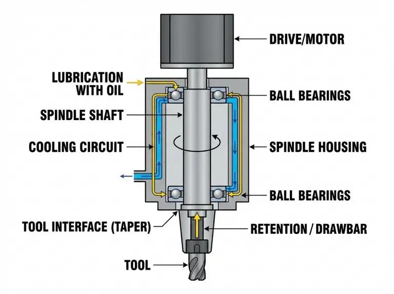
A CNC milling spindle is the rotating assembly that holds the tool and transmits power to the cutter. Milling results depend not just on the shaft spinning, but also on how it is supported, cooled, lubricated, and clamped to the toolholder. We will clarify the system boundary first so selection isn’t based only on RPM.
A spindle system includes the shaft, bearings, housing, and the tool interface. The housing also routes utilities like lubrication, cooling, and air services, so we consider it part of the reliability boundary. We verify these support systems because even the best spindle will fail with poor cooling, dirty air, or inconsistent lubrication.
Drive elements are also part of the spindle system. Speed stability under load depends on the electronics that control the spindle. A spindle might hit its top speed but perform poorly if the drive cannot maintain stable rotation during cutting. We check speed control in the operating range used for the job, not just in a no-load test.
The toolholding interface is critical because many “spindle problems” are actually interface problems. A taper centers the toolholder, and a retention mechanism pulls it into place with a specific clamping force. We check taper cleanliness, toolholder condition, and retention force before blaming the bearings. This sequence prevents avoidable damage.
Common Spindle Misconceptions
Maximum RPM is not a good predictor of milling capability. Torque, rigidity, thermal behavior, and speed control under load are what drive real-world results. Shops often choose a spindle for its speed and later find it cannot support the tool diameter, cutting load, or duty cycle. We will correct these misconceptions to help you separate marketing claims from key decision factors.
High RPM is only useful when the tool diameter and material require high surface speed and the system remains stable. A small end mill cutting aluminum might benefit from higher RPM. A large face mill, however, usually needs more torque and stiffness. We decide on speed ranges after defining the tool size, finish targets, and type of work—roughing, semi-finishing, or finishing.
Torque and power are not constant across the entire speed range. A spindle can feel strong in one speed band and weak in another, even if nameplates look similar. We prevent poor choices by checking where torque is available, especially for low-speed work that puts heavy loads on bearings and interfaces.
Runout is often seen as a “spindle spec,” but it usually comes from the taper and toolholder interface. A clean taper, a good toolholder, and stable retention can restore cutting stability without touching the spindle itself. We verify interface conditions first because this approach fixes more problems with less disruption.
CNC Milling Spindle Types and Tradeoffs
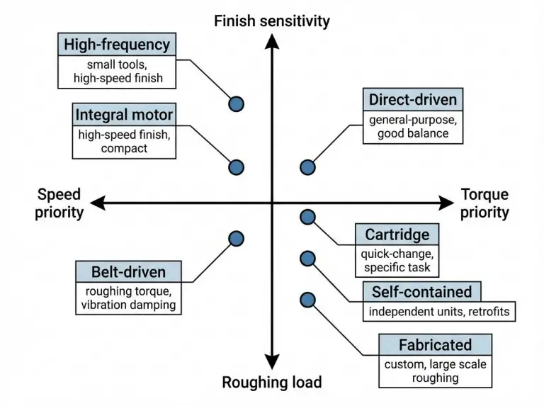
Spindle selection improves when a shop compares architectures using consistent criteria, not just speed. Milling results are most sensitive to torque, stiffness, thermal stability, speed control, and tool interface behavior. We will compare common spindle types using these dimensions so you can match each type to the right milling task.
We also separate drive transmission style from packaging style. Belt, direct-drive, gear transmission, and integrated motor describe how power gets to the shaft. Cartridge, self-contained, and fabricated describe how the spindle is built and serviced.
Belt-Driven Spindles
Belt-driven spindles are a good fit for tasks needing strong low-speed torque and robust roughing. The motor is separate from the spindle shaft and connected by belts and pulleys. Pulley ratios can match the motor’s efficient speed range to the spindle speed the job requires. Belt systems often work well in general-purpose milling where top speed is not the main goal.
However, belt systems add variables like belt condition and tension. A worn belt can create vibration that looks like chatter or bearing wear. We prevent wrong diagnoses by checking belt health when noise or finish changes unexpectedly.
Direct-Driven Spindles
Direct-driven spindles suit milling work that needs a balance of higher speed and stable power. A direct coupling removes belt-related issues and often improves consistency at higher speeds. We use direct-driven designs when finishing stability is important and the shop wants fewer belt variables to manage.
Direct drives can still transfer heat from the motor to the spindle. Thermal stability is a key factor when tolerances are tight or cycles are long. We verify cooling capacity and warm-up behavior during selection, not later.
Integral Motor Spindles
Integral motor spindles fit jobs that need a compact design, fast response, and smooth high-speed performance. The motor is built into the spindle assembly, which reduces mechanical links that can cause problems. We see motorized spindles as a system choice that must include cooling capability, contamination control, and downtime tolerance.
Service is a practical tradeoff that shops often underestimate. When a motorized spindle needs service, the process can be more complex than just swapping an external motor. We check what a service event involves before committing to this architecture to set realistic expectations.
High-Frequency Spindles
High-frequency spindles are for small-tool work where surface speed demands very high RPM. Here, chip load and vibration control are the main risks. These spindles are used for fine-feature work where tool diameters are small and high-speed stability is the top priority. We only choose this type after confirming the work does not need large-tool torque or heavy roughing.
High RPM makes the system more sensitive to toolholder balance and interface cleanliness. A minor imbalance or taper defect can become a major stability problem at high speeds. We prevent this by making balance and interface checks required steps.
Cartridge Spindles
Cartridge spindles fit platforms where modular replacement and rebuilds can reduce downtime. A cartridge design simplifies service planning if a replacement unit is on hand. We choose cartridge designs when repeatability and maintenance logistics are as important as peak performance.
Cartridge designs still rely on proper cooling, lubrication, and contamination control. A modular build does not protect bearings from poor shop practices. We verify system inputs because they determine spindle life in real-world operation.
Self-Contained Spindles
Self-contained spindles are packaged units integrated into a machine or auxiliary setup. These often appear in specialized milling machines, retrofits, or as secondary spindles. We compare options based on integration limits, tool interface compatibility, and the shop’s ability to provide stable cooling, air, and power.
The main risk is assuming the unit is “plug-and-run.” Any spindle’s performance is affected by mounting stiffness and interface cleanliness. We prevent surprises by verifying mounting rigidity and alignment early on.
Fabricated Spindles
Fabricated spindles are engineered for a specific task, space, or integration need. These designs are used when standard packages do not meet mechanical or process requirements. We only decide on a fabricated solution when the task is stable enough to justify custom engineering.
The risk is future inflexibility. A spindle optimized for one tool and speed may not work well for other jobs. We prevent this by documenting the application boundaries and acceptance criteria before committing.
Selection Inputs for Spindle Performance
Spindle selection becomes reliable when you verify a few key inputs that control cutting stability and thermal repeatability. Spec sheets have many numbers, but only a few determine if a spindle will work for your tasks. We use the inputs below to decide what to buy, how to quote, and what to check on arrival.
Speed Range and Tool Diameter
Spindle speed range becomes important after you define the tool diameter, surface speed needs, and finish requirements. Smaller tools often need higher RPM, while larger tools need lower RPM with more torque and stiffness. We clarify the tool and material needs first so speed selection is tied to the job.
Speed stability is also a requirement. The spindle must hold a stable rotation under load without creating too much heat or vibration. We verify the usable speed range for your duty cycle instead of just trusting the top number.
Torque and Power Curve Interpretation
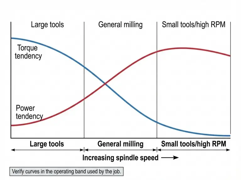
Torque and power should be seen as curves across the speed range, not single numbers. Roughing, drilling, and large-tool milling depend on the torque available in the operating band. We decide on torque needs by mapping your jobs to the speed range where the spindle must carry a load.
Power relates to how the spindle sustains work, but it still depends on speed and heat removal. A spindle can feel strong in one range and weak in another. We prevent a bad selection by confirming the spindle can handle your load profile without thermal issues or instability.
Drive Electronics and Feedback
Drive electronics and feedback determine if the commanded RPM remains stable during cutting. A spindle can meet a speed rating but cause finish and tool-life problems if speed regulation is poor. We check speed control behavior by observing cutting response in the operating band, not just with a no-load spin test.
Drive matching is also a compatibility check for specialized spindles. High-frequency and some motorized spindles may need specific drive capabilities. We prevent integration problems by verifying the drive, cooling, and protection systems as a complete set.
Bearing System Implications
Bearing system design affects stiffness, runout under load, and how heat impacts accuracy. A bearing setup made for high speed can behave differently than one made for heavy cutting. We compare bearing systems based on your tasks, because the right strategy depends on your priority: roughing rigidity, finishing smoothness, or high-speed performance.
Heat growth is a hidden variable in many tolerance problems. Bearings create heat, and the spindle structure expands as it gets hotter. We verify warm-up behavior and thermal repeatability to keep measurement and finishing work consistent.
Cooling and Lubrication Fit
Cooling and lubrication are selection inputs because they control bearing conditions and thermal drift. A spindle used for a high duty cycle needs stable heat removal and consistent lubrication. We decide on the right support system by checking your duty cycle, environment, and maintenance habits.
Lubrication strategy also sets service expectations. Some designs need minimal user action, while others depend on controlled air and oil. We prevent early failure by verifying air quality, filtration, and the shop’s ability to maintain the support system.
Tool Interface and Clamping Verification
The quality of the spindle-to-tool interface often determines whether a spindle delivers a predictable finish and tool life. The taper interface, retention force, and toolholder condition control stability under load. We verify the interface and clamping before other diagnostics because these faults are common and easy to fix.
Taper size is also a decision input. It affects tool system mass, clamping behavior, and the tool inventory a shop can support. A taper choice should be checked against the machine setup, toolholder specs, and cutting load. We treat taper size as a key selection factor, not a late detail.
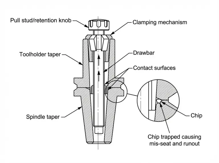
Taper and Holder Interface Checks
Concentric seating depends on a clean, undamaged taper and a matching toolholder. Minor debris on the taper face can create runout and mark the surface during clamping. We prevent this with a daily cleaning routine and by treating any unknown toolholder as a process risk.
Toolholder wear and fretting are warning signs. A holder that repeatedly slips or seats poorly can cause chatter and an unpredictable finish. We check holder condition and interface fit before blaming spindle bearings.
Drawbar and Retention Checks
Retention behavior keeps the toolholder seated during milling. Weak retention can cause micro-slip, which appears as chatter, fretting, and inconsistent finish, even if runout looks fine at rest. We prevent this by checking retention force on a routine schedule and investigating any sudden change in how a tool seats.
Retention is also tied to cleanliness. Chips in the interface can interfere with seating and reduce clamping force. We check chip evacuation and air blast function during tool changes because these factors protect the taper surface.
Toolholder Balance Expectations
Higher spindle speeds are more sensitive to imbalance in the holder and tool assembly. Vibration that seems like a spindle issue can come from an unbalanced holder, a bent tool, or a poor assembly. We prevent wrong diagnoses by validating balance practices when milling at higher speeds.
Balance requirements depend on the speed range and tool assembly. Not every job needs the same level of balance control. We decide on a balance discipline based on the operating band and finish requirements.
Taper Cleanliness Actions
Taper cleanliness is one of the most effective ways to ensure spindle reliability. A single trapped chip can create runout and permanently damage the ground surface when clamped. We prevent that damage with a routine that includes wiping, visual inspection, and verifying chip clearing.
Cleaning must not be abrasive. The goal is to remove debris without changing the taper’s geometry. We verify that the cleaning method is compatible with the interface and used consistently across all shifts.
Operating Conditions and Maintenance
Spindle downtime is often prevented by controlling heat, contamination, vibration, and load. Most spindle failures give early warnings, but shops miss them without standard checks. We prevent avoidable failures by turning operating conditions into repeatable habits.
Warm-Up and Thermal Stabilization
Warm-up is important because a cold spindle behaves differently than a warm one. Jumping from a cold start to high speed can stress bearings and create unstable Z-axis behavior during finishing. We prevent this with a warm-up routine that gradually increases speed to stabilize the system before tight-tolerance work.
Thermal stabilization also supports repeatable inspection. If a measurement is taken while the spindle is still drifting thermally, the results will be inconsistent. We verify warm-up behavior during process planning, not just as a maintenance task.
Shop Air and Air-Oil Quality
Contamination control is a primary driver of bearing life in systems that use air and oil. Dirty or wet air can carry water and particles into sensitive areas, speeding up wear. We prevent this by verifying air quality, filtration, and dryness. We treat air system neglect as a direct cause of spindle failure.
The shop environment matters even for grease-lubricated designs. Chips and coolant mist can get into interfaces and cause corrosion. We verify sealing and cleaning practices around the spindle nose to protect both toolholding and bearings.
Vibration and Imbalance Controls
Vibration in milling is a problem for both the finish and the bearing life. Chatter marks on parts often mean increased bearing loads and faster wear. We prevent damage by separating likely sources, including the tool assembly, workholding rigidity, and spindle interface condition.
Machine rigidity and foundation also matter. A spindle can seem unstable when the real problem is in the setup path. We verify the setup path before assuming the spindle needs service.
Load and Duty Cycle Habits
Duty cycle is important because continuous operation at extreme conditions increases heat and bearing loads. Even a capable spindle can wear out early if it’s constantly run at maximum output. We prevent a shortened life by matching spindle use to the job mix and considering temperature and lubrication.
Load management is also a planning task. Tool choice and toolpath strategy change spindle load. We verify that process plans are compatible with the spindle’s intended operating band instead of forcing it to handle avoidable overloads.
Stop-Now Symptoms
Certain symptoms mean you should stop immediately, as continued operation can turn a small service event into a major rebuild. Sudden abnormal noise, a rapid temperature rise, or a sharp change in finish can signal bearing distress. We prevent secondary damage by defining a “stop-now” rule and checking the tool interface and retention first.
We also separate gradual drift from sudden changes. Sudden changes often point to contamination, damage, or a failed support system. We verify these causes before taking the spindle apart.
Conclusion
A CNC milling spindle decision becomes repeatable when you treat the spindle type, tool interface, drive stability, and support systems as one complete set of inputs. We use the same decision process for prototypes and production because the failure modes are the same. The goal is a spindle system that stays stable for your duty cycle and tool mix, not just one with a great spec sheet.This is especially important when selecting setups for cnc plastic milling services, where heat, chip evacuation, and surface finish can be more sensitive to spindle stability.
FAQ
What is a CNC milling spindle?
A CNC milling spindle is the rotating assembly that holds the tool and provides controlled rotation for milling. Accuracy depends most on the bearing system, spindle nose geometry, drive stability, and tool interface quality.
Which spindle type fits roughing vs. finishing?
Heavy roughing favors spindles with stable torque and stiffness at lower speeds. High-speed finishing favors spindles that are smooth and thermally stable at higher speeds. The right choice depends on the tool, cut load, and duty cycle.
How do I interpret RPM, torque, and power?
RPM shows how fast a tool can spin, but success depends on stable rotation under load. Torque is the twisting force for larger tools and heavier cuts, and it varies with speed. We look at power and torque as curves and check them in the operating band your jobs use.
What causes sudden poor surface finish?
A sudden change in finish is often from toolholder seating issues, debris in the taper, or weak retention. It is less likely to be slow bearing wear. We check interface cleanliness, holder condition, and retention first.
What checks reduce runout and vibration?
Runout and vibration risk decrease when you control taper cleanliness, verify toolholder condition, and confirm stable retention. Also, check holder balance for the spindle’s operating speed and verify the rigidity of the entire setup.
What actions reduce unplanned downtime?
Consistent warm-up routines, stable cooling and lubrication, and strict contamination control prevent many early bearing failures. Daily taper cleaning also reduces damage that can lead to expensive service.