
CNC milling cutting tools determine if a programmed toolpath results in a stable cut, a clean surface, and a predictable tolerance. A machine can position with accuracy, but the cutter’s geometry, material, and setup dictate the cutting forces, chip control, and final finish quality.
Tool selection is a system decision, not just a catalog choice. The cutter family must match the operation, the workpiece, and the setup’s rigidity. When these factors are clear, tool life and cycle times become much more predictable.
Milling Cutter Families
CNC milling cutter families are easiest to choose when you tie each tool to a specific cutting direction, feature type, and chip path. We can separate the most common tools by what they cut well, what they cannot do safely, and why they fail when used incorrectly.
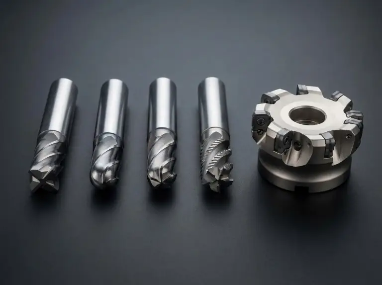
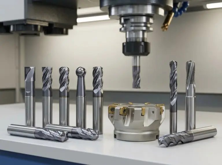
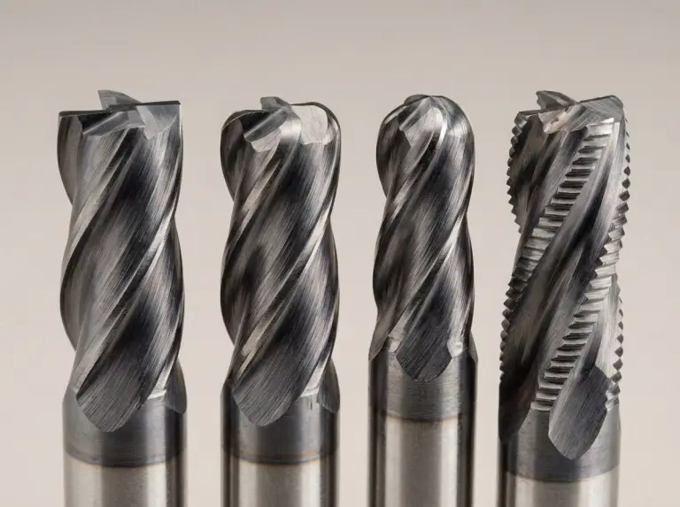
End Mills
End mills are the default choice for pockets, slots, and side-wall finishing because they cut with both their end and side. Square end mills create flat floors and sharp internal corners where geometry allows. Corner-radius (bullnose) end mills reduce edge chipping and improve tool life in tougher materials.
Ball end mills are standard for 3D surfaces because their rounded tip controls scallops on contoured toolpaths. Roughing end mills remove stock quickly by breaking chips, but they typically need a separate finishing pass to meet surface requirements.
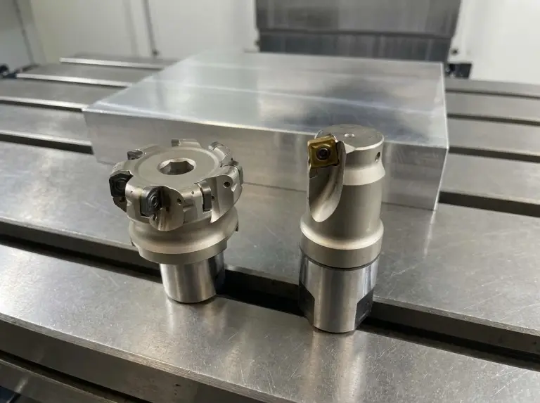
Face Mills and Fly Cutters
Face milling tools are used to flatten a broad surface quickly with a stable load shared across multiple cutting edges. Face mills are often indexable and excel at surfacing stock to a consistent plane. However, they are not meant for plunging deep into material.
Fly cutters also produce flat faces and are often used when a simple, single-edge tool is acceptable. We consider face mills and fly cutters “planar surfacing tools,” and choose between them based on the surface target, machine stability, and process consistency.
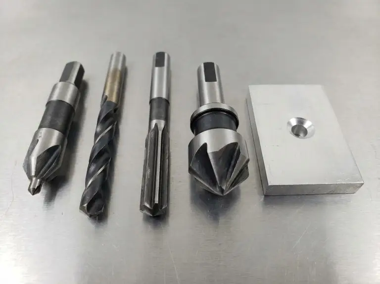
Hole-Making Tools
A reliable hole-making process starts with positioning, then creating the hole, and finally finishing it to the correct size and edge condition. Spot drills or center drills improve location accuracy and reduce drill walking. Twist drills then create the main hole efficiently.
Reamers are used after drilling when the hole diameter and surface finish need tighter control than drilling provides. Countersink tools and chamfer mills finish the entry edge for fasteners or for deburring. We recommend choosing standard angles when possible to avoid having too many tool variations.
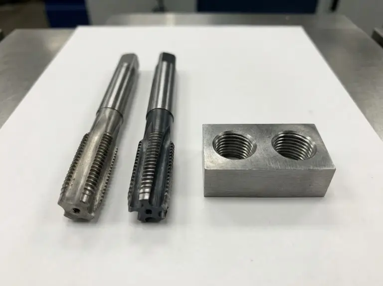
Threading Tools
You can create threaded holes by tapping or thread milling. The better choice depends on the material, hole type, and your risk tolerance. Cutting taps remove material and create chips. Forming taps deform material, avoiding chips, but require the right hole size and a ductile material.
Thread mills create threads through interpolation. This method is useful when thread quality and tool breakage risk are major concerns. We confirm our threading choice by checking the thread specification, hole depth, chip evacuation risk, and whether one tool can handle multiple thread sizes.
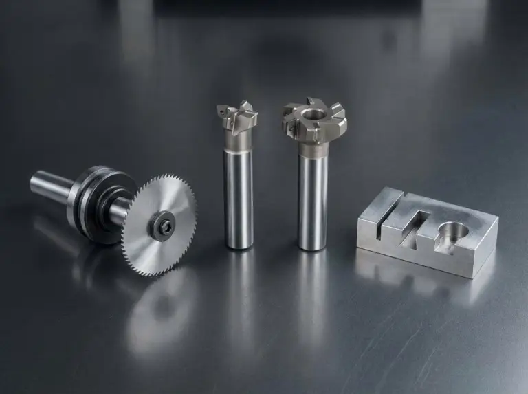
Slot and Undercut Tools
Undercuts and T-slots often need a special cutter designed to reach behind a wall that an end mill cannot. Keyseat cutters can create these features without re-fixturing the part, which saves on setup costs and reduces alignment risk.
Slitting saws cut deep, narrow slots and can also perform parting operations in some workflows. Dovetail cutters create dovetail undercuts. Keyway or Woodruff-style cutters are used for specific keyseat features where a standard end mill cannot form the correct profile.
Specialty Cutters
Specialty cutters appear when geometry or legacy processes require them, even in modern CNC shops. Gear cutters and involute-style cutters are used for certain gear features when the process plan demands them. We treat these as “feature-specific tools” rather than general-purpose cutters.
Slab mills, side-and-face cutters, and hollow mills are less common in everyday CNC work but remain relevant in certain setups. Knowing their names helps you recognize them on tooling lists and avoid using the wrong modern tool as a substitute.
Further Reading:CNC tool holder types
Tool Materials and Coatings
The choice of tool substrate and coating sets the practical limit for heat resistance, edge toughness, and wear rate in CNC milling. We compare materials as a trade-off between toughness, hardness at high temperatures, and cost, because the best material depends on the cut.
Carbon steel tools are a low-cost option for low-speed work. They are not typically used for modern high-speed CNC milling in harder metals but still appear in simple operations where heat is not a major factor.
High-speed steel (HSS) offers better toughness than carbide and can tolerate shock and vibration well. HSS is often chosen when rigidity is low, quantities are small, or the workpiece is soft and does not justify the cost of carbide.
Carbide is the top choice for CNC milling because it stays hard at high temperatures and allows for faster cutting speeds. However, carbide is less forgiving of chatter and runout. We always check rigidity, holder condition, and stickout before assuming carbide will perform better than HSS.
Ceramics, CBN, and diamond-family tools are for specific cases where heat and hardness are the main challenges. These tools require tight control over the setup and process. They should be selected with supplier guidance because their failure modes are often sudden.
Coatings solve problems related to wear, heat, and material adhesion; they are not universal upgrades. Common coatings include TiN for general wear, TiCN for improved wear resistance, and AlTiN/TiAlN for higher heat resistance in tough cutting conditions.
We verify coating choice against the workpiece material, coolant strategy, and target tool life instead of trusting marketing claims. Supplier catalogs list coating options, flute counts, and hardness ranges, and this information should be confirmed against the actual machining setup.
Geometry and Setup Factors
Tool geometry and setup rigidity determine whether cutting forces remain stable or lead to chatter, deflection, and edge chipping. We check the key geometry choices that control success, especially for small tools and deep features.
Flute Count and Chip Evacuation
Flute count balances chip space and core strength. Fewer flutes provide larger channels for soft materials that create a lot of chips. More flutes add stiffness and distribute the load in harder materials where chip thickness must be controlled.
Chip evacuation is a process requirement, not a preference. If chips cannot exit the cut, heat builds up, and tool life plummets, regardless of the tool material.
Tool Diameter and Internal Radii
Tool diameter is limited by the smallest internal radius and the narrowest slot in the part design. A large tool removes material faster but cannot fit into tight corners. A two-stage approach often works best: rough with a larger tool, then finish corners with a smaller one.
Fillets and inside corners are very important because they directly determine which end mill diameters are practical. We clarify this early in the quoting process because changing a fillet radius in CAD is often cheaper than using a fragile micro tool and accepting a longer cycle time.
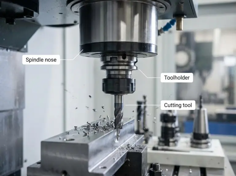
Stickout, Holders, and Runout
Tool stickout, or the length beyond the holder, is a major cause of chatter and deflection. Keeping the tool as short as the feature allows improves the finish and protects the cutting edges, especially with carbide.
Runout turns a multi-flute tool into an overloaded single-flute tool because one edge does most of the cutting. We check holder cleanliness, collet condition, and spindle taper hygiene before blaming the tool for premature wear.
Coolant, Heat, and Thermal Shock
Your coolant strategy should match the tool material and the cut’s thermal cycle. Interrupted cuts repeatedly heat and cool the edge, which can cause thermal cracking. Depending on the tool and material, an air blast or controlled coolant delivery may be a better choice.
Heat management is also a chip problem. If chips carry away heat and the cut stays clear, tool life is stable. If chips are recut, the edge wears quickly even at conservative settings.
A Workflow to Prevent Errors
A consistent tool selection workflow reduces scrap by turning “tool choice” into a series of verifiable steps. We decide on tooling in the same order most shops run a job: face and datum first, then bulk removal, feature finishing, and finally edge conditioning.
Start by labeling each feature as planar surfacing, pocket/wall milling, hole making, or a specialty form/undercut. Then, assign the cutter family that performs that action. Only after that should you choose the diameter, flute count, and coating.
Verification points to use:
- The smallest internal radius and slot width allow for the planned tool diameters.
- The setup rigidity supports the planned stickout and flute count.
- Chip evacuation is possible with the chosen coolant/air strategy and tool geometry.
- The tool list minimizes changes without forcing the use of risky micro tools.
We also recommend adding a “tooling spec line” to the process sheet so purchasing and programming stay aligned. This line should include tool type, diameter, flute count, flute length, overall length, coating, and holder style.
Wear Patterns and Failure Modes
Tool wear control is most effective when you treat wear as an early warning signal, not a surprise break. We prevent downtime by linking common wear patterns to the first corrective action that usually fixes them.
Flank wear is a normal abrasion pattern that signals a tool has reached its expected life. As flank wear grows, cutting forces rise and the finish worsens. Scheduled tool changes are often better than waiting for failure.
Chipping usually points to vibration, interrupted cuts, or a lack of rigidity. First, check for ways to reduce stickout, control holder/runout issues, and adjust the cutting strategy before switching to a different tool.
Built-up edge is common in gummy materials and results in a poor finish and unpredictable cutting. Improving chip evacuation, using sharp geometry, and choosing the right coating can stabilize the cut.
Thermal cracking appears when an edge cycles between hot and cold. We check the coolant strategy and entry/exit conditions because the “right coolant” depends on the specific tool material, workpiece, and cut pattern.
Proper storage and handling also matter. Carbide edges chip easily when tools hit each other. Dedicated organizers, sleeves, and clean toolholders protect the cutting edge and help keep runout low.
Conclusion
At Yonglihao Machinery, we understand that CNC milling tool performance depends on perfectly matching the tool family, material, and setup rigidity with the part features and chip behavior. The most reliable results come from selecting the right cutter type first, then fine-tuning the geometry and coating for the specific cutting risk.
We can summarize tool selection as a repeatable, professional process: define the operation, pick the cutter family, constrain the diameter by geometry, strictly control stickout and runout, and verify chip evacuation. This rigorous method reduces guesswork, ensures consistent surface finishes, and makes tool life predictable.
As a professional prototype manufacturer, Yonglihao Machinery is dedicated to providing you with the highest standard of CNC machining and milling services. Whether your project requires complex geometries or tight tolerance control, we have the experience and technology to make it a reality. If you’re looking for a reliable machining partner, contact us today, and let our superb craftsmanship safeguard your next project!
Continue Reading: How To Select Cutting Tools For CNC Machining?
FAQ
What are the most common CNC milling tools?
End mills, face mills, and drills are the most common tools because most parts need surfacing, pocketing, and holes. A typical tool list also includes a chamfer tool for edge breaks and a tap or thread mill. Tool variety increases when parts have undercuts, keyways, or special forms.
End milling vs. face milling: what’s the difference?
End milling uses the end and side of an end mill to cut pockets, walls, and profiles. Face milling removes material across a large flat area with a face mill. The choice depends on whether the main feature is a broad plane or a contained pocket or wall.
How do I choose flute count for aluminum vs. steel?
Aluminum often needs fewer flutes to maximize chip space and reduce chip welding. Steel and tougher alloys often need more flutes to increase tool stiffness and distribute the cutting load. The right answer still depends on chip evacuation and rigidity, so always verify the flute count.
When should I use a reamer instead of a drill?
Use a reamer when the hole size and surface finish must be more precise than what a drill can provide. Drilling creates the hole, but reaming brings it to the final size with a better finish. Reaming should be planned as a second step after the hole is drilled.
Tap or thread mill: which is safer?
Thread mills can be safer when chip control, thread quality, or tool breakage is a concern. The tool path is controllable, and the tool is less likely to seize than a tap. Taps are fast but are sensitive to hole size, material, and chip evacuation. The better choice depends on the specific job.
How can I reduce tool changes without risk?
To reduce tool changes, design parts with standard tool sizes and reasonable internal radii. Larger tools can rough out material quickly, while smaller tools only finish the tight corners that require them. Plan tooling to minimize the use of micro tools unless a feature truly demands it.