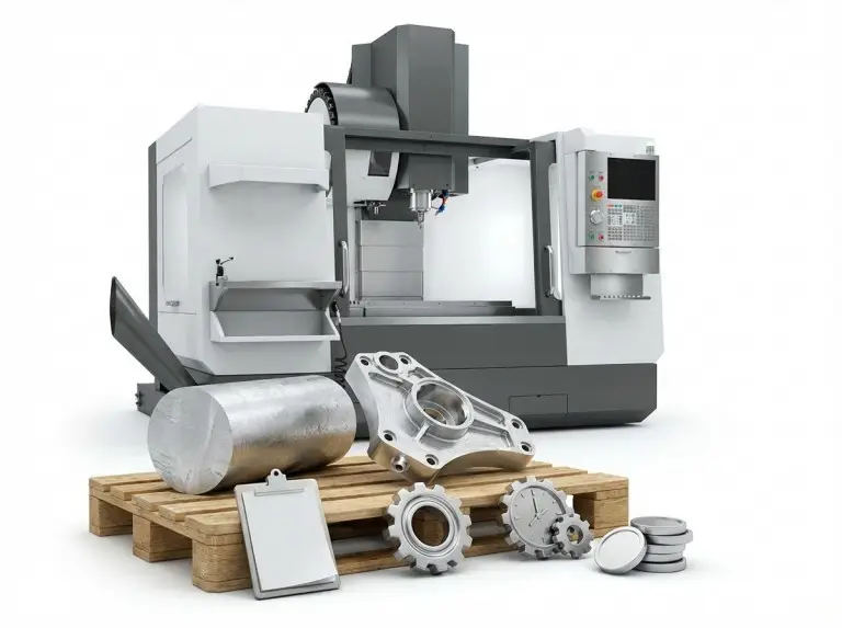

A good decision on a CNC milling or turning machine starts with clear part details. You need to define the part’s geometry, critical features, and setup goals before choosing a machine. At Yonglihao Machinery, we use this input-first approach. Vague part definitions lead to wrong machine choices and avoidable rework. This guide compares CNC milling, turning, and combined methods. We will look at mechanics, part fit, machine types, and key verification steps.
Both CNC milling and turning remove material from a workpiece using programmed controls. The processes often start with a CAD model and a toolpath plan. However, this article does not teach programming. Instead, we focus on the shop-level questions that affect outcomes: what rotates, what sets the datums, and what must be held in a single setup.
Defining Machine Terms
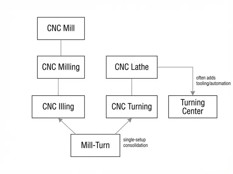
Labels like mill, lathe, turning center, and mill-turn can be confusing. A CNC lathe, CNC turning, and a turning center have overlapping abilities. Turning is the core operation that creates round geometry around a spindle axis. “Lathe” is the common name for this machine type. A turning center usually has more tooling and automation, but you should verify its capabilities based on your part’s features, not marketing terms.
A CNC mill is a machine type, while CNC milling is the process. In milling, a rotating cutter removes material as the machine moves along different axes. People often see milling as the default approach because it works well for many prismatic parts. To avoid confusion in quotes, we list the part’s functional datums and features before naming a machine.
A mill-turn machine combines capabilities. It is not always an upgrade. Mill-turn is best when turned and milled features must be closely related without re-clamping the part. We clarify this early so teams don’t choose a complex process when a simpler, split process would work.
A simple check is to ask if the part needs non-turning features that must reference the turning axis in the same setup. If you have cross-holes, flats, or keyways that need tight location to the spindle axis, a turning center with extra abilities or a mill-turn plan may be the right choice. If those features are not critical or can handle a second fixture, a split process is often easier to validate.
Cutting Mechanics of Milling vs. Turning
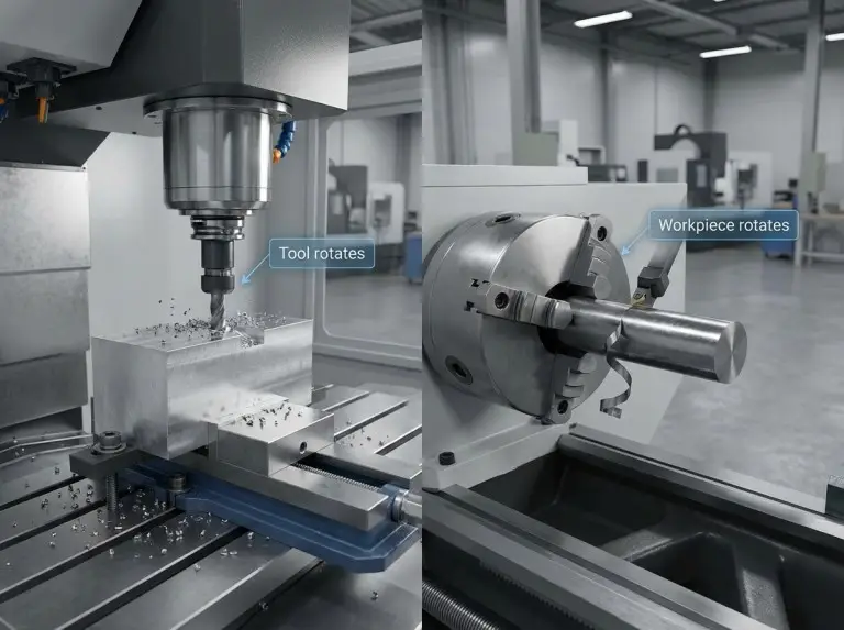
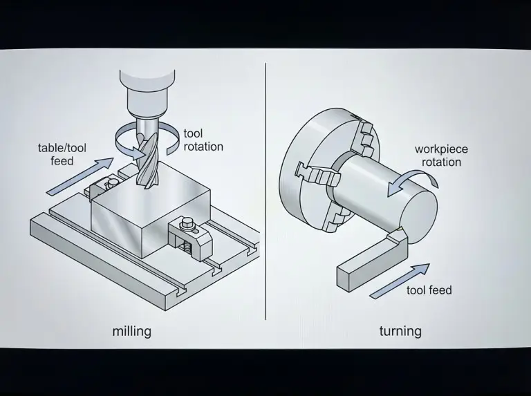
CNC milling uses a rotating cutter to remove material while a fixture holds the workpiece. The cutter usually has multiple edges. The machine feeds the tool or the table along programmed axes to create flats, pockets, slots, and profiles. We see milling as the best fit for prismatic parts where flat datums control the part’s function.
CNC turning spins the workpiece while a cutting tool feeds into it. Turning often uses a single cutting edge to create outer diameters, inner diameters, faces, and tapers that share one axis of rotation. We use turning when coaxial features and stable roundness are the main functional needs.
These different mechanics affect how datums work in production. Milling depends on fixture repeatability and datum transfer across setups for parts with multiple faces. Turning relies on the spindle axis and a controlled gripping strategy. How you re-grip and support the part often determines the quality.
Part Geometry and Feature Fit
Radial symmetry is the quickest way to choose between turning and milling. Shafts, bushings, and disk-like parts usually fit turning well when concentric relationships are the main functional drivers. We still check if any secondary features need milling and if they must stay indexed to the turning axis.
Prismatic geometry is the fastest way to screen for milling. Parts with mostly flats, pockets, and cavities are typically a good fit for milling. We check if round features are truly functional cylinders or just clearance holes that can be drilled or interpolated.
Key feature types make the selection more reliable than industry labels. Flats, pockets, and grooves usually point to milling. Cylindrical surfaces, conical surfaces, and coaxial bores usually point to turning.
Single-setup needs can override the “obvious” choice. A turned part might have milled flats or cross-features. The location of these features relative to the spindle axis could control how the part performs in an assembly. We decide whether to split or combine operations based on setup risk and the inspection plan, not just convenience.
|
Decision Input |
Milling Tends to Fit When |
Turning Tends to Fit When |
What We Verify Next |
|---|---|---|---|
|
Primary Geometry |
Prismatic, planar datums dominate |
Radial symmetry dominates |
Functional datums and controlling axis |
|
Feature Emphasis |
Pockets, slots, planar faces, profiles |
OD/ID, tapers, faces, concentric grooves |
Which features must share one setup |
|
Main Risk Driver |
Multi-face alignment across setups |
Coaxiality and re-grip stability |
Workholding repeatability and support plan |
|
Typical Routing |
One or more milling setups |
Turning with possible secondary ops |
Whether consolidation reduces measurable risk |
Machine Types for Milling and Turning
Choosing the right machine family is important. It affects access, setup count, and stability. We group families by spindle orientation, axis access, and how the workpiece is supported. This helps avoid comparing machines that solve different problems.
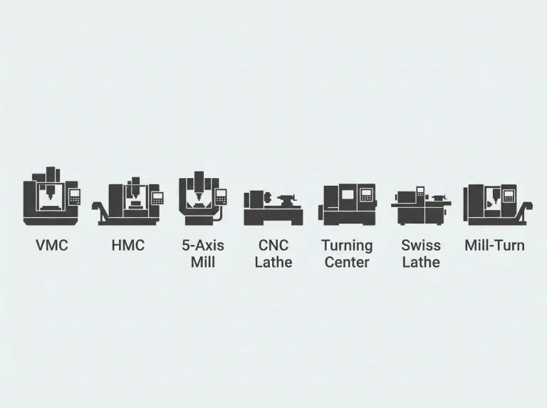
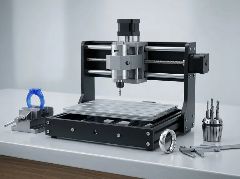
Vertical Machining Center (VMC)
A vertical machining center (VMC) suits many prismatic parts with top-side access. The setup is often simple for drilling, pocketing, and surfacing. We check if multi-face needs will force several re-clamps, which increases alignment risk. A VMC plan works well when the datum scheme and fixture repeatability are clear.
Horizontal Machining Center (HMC)
A horizontal machining center (HMC) is good for multi-face work. It can present different sides with consistent referencing. Chip evacuation can also be better because chips fall away from the cut. We consider an HMC when multiple faces must be held to each other with predictable datum transfer.
Five-Axis Milling Machine
A five-axis milling machine adds angular access that can reduce re-clamps. This is useful when features sit on multiple faces or need compound-angle access. We choose five-axis routing based on access and setup reduction, not because more axes are always better. Planning for five-axis work also adds collision and verification demands.
CNC Lathe and Turning Center
A CNC lathe is the basic platform for turning rotational parts. A turning center can add capabilities for secondary features. We use this machine family when coaxial relationships drive function and the spindle axis is the main datum. Workholding and support often decide turning outcomes more than the machine label itself.
Swiss-Type Lathe
A Swiss-type lathe supports small, long parts by guiding the work close to the cut zone. This reduces deflection when the length-to-diameter ratio makes standard chucking unstable. We consider Swiss routing when the stability of slender sections is the primary constraint. This machine is effective for specific part families, not every turned part.
Mill-Turn Multitasking Center
A mill-turn center fits parts that are mainly rotational but include milled features that need to reference the turning axis precisely. The value comes from combining setups and controlling indexing. We choose this path when re-clamping is the main quality risk. This consolidation also increases the complexity of routing and verification.
Multi-Spindle Lathe
A multi-spindle lathe is for high-volume turning. It uses parallel operations to reduce per-part time. The decision is driven by production strategy, not just geometry. We see this as a later-stage optimization choice that requires stable demand and disciplined tool management.
Laser-Integrated Turning Platforms
These platforms combine turning with laser-based operations for specific workflows. The value is usually in reducing handoffs or secondary steps for certain parts. We view this as a niche option and verify that the laser step is truly required for the part.
Further Reading:Most Common Types of CNC Machines
Verification Steps to Avoid Over-Configuration
A reliable selection starts with part inputs, not machine features. We decide the routing based on functional datums, critical features, setup count, and the inspection method. This prevents choosing a complex machine when the part doesn’t need it.
Setup count is a practical risk driver. Each extra clamp can add alignment error and handling damage. We verify which feature relationships must be made in one setup to protect the part’s function.
Material behavior is another verification step. Hardness, ductility, and heat sensitivity can change stability and surface risk. We verify the exact material grade, stock form, and surface needs before finalizing the process.
Complex capability is not always the best fit for a simple part. Over-configuring can increase programming and inspection effort without improving functional results. We prevent that by matching the minimum viable capability to the part’s actual needs.
Conclusion
Comparing CNC milling and turning machines is effective when the choice is driven by part geometry, feature relationships, and setup risk. We separate milling, turning, and mill-turn choices with a consistent flow. First, clarify the mechanics. Then, map the geometry fit, select a machine family, and verify setup and inspection feasibility. This approach keeps decisions aligned with functional needs, not generic machine labels.
For a clean quote and routing recommendation from a China CNC milling service provider, provide a drawing or 3D model, material specification, critical tolerances, surface requirements, expected quantity, and the features that must be held in one setup. We use these inputs to find the right solution without over-complication.
Further Reading:
FAQ
What is the main difference between CNC milling and turning?
CNC milling rotates the cutting tool, while CNC turning rotates the workpiece. Milling is often for prismatic parts with flats and pockets. Turning usually fits parts dominated by concentric features. The best choice depends on functional datums and setup goals.
When should a part be turned first and then milled?
A part should be turned first when concentric geometry defines its function and the spindle axis is the main reference. Milling can follow for features like flats or cross-holes. This split should be verified by how the part will be re-clamped and inspected.
When does a mill-turn machine make sense?
A mill-turn machine is useful when turned and milled features must stay tightly related in one setup. Consolidation is best when re-clamping creates an unacceptable alignment or handling risk. The benefit depends on the feature relationships and inspection method.
Is a CNC lathe the same as a turning center?
A CNC lathe is the basic machine for turning. A turning center often has more tooling and automation options. The terms overlap, so you should verify capability by the required operations and workholding method. We avoid confusion by listing features instead of relying on labels.
How do geometry and features drive the machine choice?
Radial symmetry points toward turning, while prismatic geometry suggests milling. Specific features refine the decision. For example, pockets and planar profiles suit milling, while tapers and coaxial bores suit turning. The final routing should be verified by which features must share one setup.
What information should I provide to choose the right CNC routing?
A complete part definition needs a drawing or model, material specification, critical tolerances, and surface requirements. The quantity range and stock form also influence the setup strategy. We use this information to decide on the minimum viable capability and prevent over-configuration.