
Planning for plain milling works best when you define tooth engagement, the target flat surface, and setup stiffness before picking a cutter. We see plain milling used when a wide plane needs to be sized as a functional face or a reference for later steps. But this operation gets unpredictable if teams mix up terms, skip alignment checks, or pick a cut direction without thinking about backlash and clamping force.
This article focuses on plain milling as a peripheral method for making flat surfaces. We cover the terms, clear up misconceptions that lead to bad choices, and look at the trade-offs driving cutter and setup decisions. We also provide verification tables and defect mapping. This helps you review and repeat the process instead of just “tuning by feel.”
Plain Milling Definition
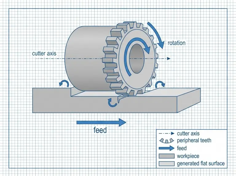
Plain milling is a peripheral operation. It creates a flat surface with the cutter axis parallel to the machined plane. Many shops also call this slab milling. Sometimes, people use “surface milling” loosely. Because of this, you must define the process by cutter engagement, not just the label. We treat plain milling as a long-travel cut using peripheral teeth. It prioritizes stable chip formation across a wide area.
Use plain milling to create a broad, flat surface. This surface can serve as a datum, a mating face, or a thickness-controlled plane. It is not the best choice for pockets, cavities, or complex contours. Those features need different tools and paths. A process plan remains clear when the traveler states the axis-to-surface relationship, engagement type, and the surface’s role.
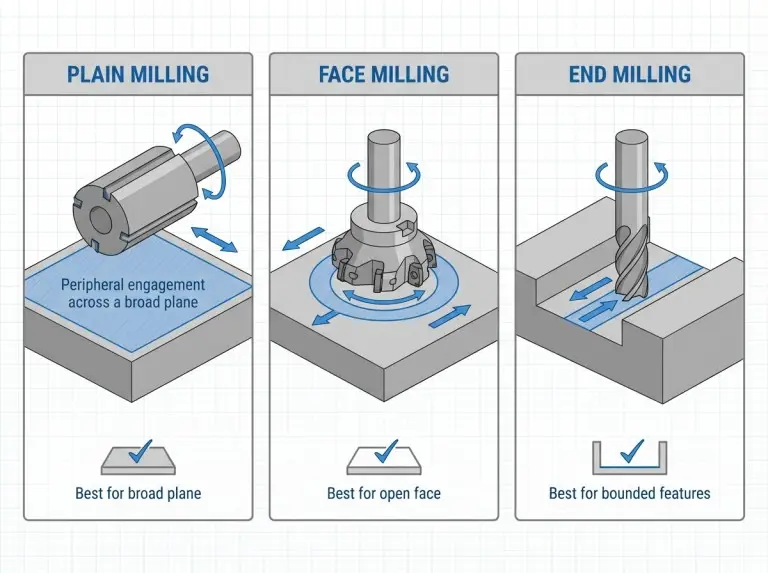
Plain milling and face milling both create flats, but they work differently. Face milling usually cuts perpendicular to the tool axis. Plain milling cuts parallel to it. This changes the contact arc, torque demand, and surface texture. End milling can also make flats. However, you typically choose end milling when features like walls or pockets limit the surface, or when access is tight.
Plain Milling Terms: Slab and Surface Alignment
Plain milling and slab milling usually refer to the same family of operations. “Surface milling” can be vague. It might mean “making a surface” or be a synonym for slab milling. Always check what is intended. If there is doubt, describe it as “peripheral-tooth flat milling with the tool axis parallel to the surface.”
Plain vs Face Milling: Flats and Width Coverage
Plain milling is a good option when you can sweep a wide plane efficiently with a stable mount. Face milling is often better when the setup favors an axis-perpendicular approach, or when you need a specific finish pattern. The right choice depends on how open the workpiece is, the cutter’s reach, and stiffness.
Plain vs End Milling: Beyond Broad Planes
Plain milling works best when the cutter has a clear path with consistent engagement. End milling is practical when bosses, walls, or interrupted edges block a wide peripheral cutter. To play it safe, check access and stability first. Then decide if plain milling fits the part geometry and inspection needs.
Further Reading:Difference Between End Milling and Face Milling
Plain Milling Misconceptions: Rework and Scrap Risks
Quality problems often come from shortcuts. These shortcuts ignore engagement mechanics and setup limits. Teams often assume “any flat surface” means face milling is the only right way. This creates mismatched expectations for tooling, burrs, and texture. Another error is thinking spindle speed will fix chatter. Often, the real cause is stiffness, runout, or poor support.
A third mistake is believing you can fix setup issues after a heavy first pass for free. Plain milling loads the workpiece in one direction over a long travel. Weak clamping can cause movement, taper, or chatter bands. These are costly to remove. A better approach is to verify alignment and runout first. Then, start with a controlled pass to prove stability.
“Any Flat Surface Equals Face Milling” Misconception
A flat surface is a result, not a process definition. Both plain and face milling can achieve flatness. However, tooth engagement and force directions differ. Verify your choice against the surface’s role, access limits, and acceptable texture patterns.
More RPM Fixes Chatter Misconception
Chatter is mostly about stability, not speed. Changing spindle speed might move a cut away from resonance. But speed can also raise heat and worsen vibration if chip thickness and support are unstable. Check tool overhang, mounting rigidity, and engagement width before changing speed and feed variables.
Setup Fixes After First Pass Misconception
A heavy first pass can lock in distortion or vibration patterns. The surface might look “close,” but the part could lose thickness margin. It might need rework that breaks the plan. A controlled first pass is the safest way to scale up material removal.
Cutter Selection: Setup and Parameters in Plain Milling
Plain milling cutter selection only works when you tie geometry and mounting to stiffness, chip formation, and the surface role. Cutter width, tooth pitch, helix, and tooth count all affect cutting force and chatter risk. Mounting is critical. Peripheral cutters amplify runout over long travel.
Practical guides often group plain milling cutters into two buckets: heavy-duty for removing stock, and light-duty for better finish control. This distinction doesn’t promise results. Verify your choice with toolmaker data and machine capability. Compare engagement stability, torque margin, and surface expectations.
The table below summarizes the decision logic.
|
Decision point |
What to compare |
What to verify before committing |
|---|---|---|
|
Heavy-duty vs light-duty cutter |
Tooth spacing and stock removal vs finish control |
Chip evacuation, torque margin, and stability |
|
Arbor-style vs holder-only support |
Support stiffness vs access constraints |
Runout, overhang length, and interface seating |
|
Climb vs conventional direction |
Force direction, burr orientation, and backlash |
Backlash risk, clamp direction, and exit support |
|
Wider vs smaller engagement |
Pass count vs cutting force and chatter margin |
Stability during a test pass and heat management |
Coarse vs Finish Intent
Cutters for heavy stock removal use fewer tooth engagements per revolution. Cutters for surface control use more engagements. They rely on stable chip thickness rather than brute force. Verify the intent against the material, stiffness, and inspection standards.
Arbor-Mounted Setups
Horizontal, arbor-supported setups provide strong support for wide cutters if alignment is controlled. CNC adaptations work too, but you must verify spindle interface stiffness and runout under load. Treat mounting as a variable you can control. Runout often drives repeating surface patterns.
Cut Direction Selection
Climb milling can reduce rubbing and support a stable finish. This works when the machine condition and clamping control the cut. Conventional milling is safer when backlash might pull the workpiece into the cutter. Choose the direction that matches your machine, clamping force, and burr tolerance.
Parameter Trade-Offs
View feed, speed, and engagement as a chip formation and stability problem. Too little chip thickness can increase rubbing and built-up edges. This hurts the finish and wears the tool. Too much engagement can overload the setup and cause chatter. Reducing engagement is often the cleanest first fix.
Further Reading:How To Select Cutting Tools For CNC Machining?
Defect Prevention in Plain Milling
Outcomes improve when setup checks target known failure modes. A plain milled plane often becomes a reference for later steps. A bad reference plane causes errors down the line. Verification is faster than rework.
Use the checklist below before and during the first pass.
|
What to verify |
Why the check matters |
What “good” looks like |
|---|---|---|
|
Workpiece support |
Long forces can bend thin sections |
Support points prevent deflection across full travel |
|
Clamp direction |
Force direction changes with cut direction |
Clamps resist force without causing distortion |
|
Datum and parallelism |
Flatness depends on correct referencing |
Datum surfaces are clean, seated, and aligned |
|
Cutter seating |
Small seating errors become repeating marks |
Seating faces are clean before tightening |
|
Runout at periphery |
Runout causes uneven loading and lines |
Runout is measured and corrected |
|
Tool overhang |
Overhang increases chatter risk |
Overhang is minimized within limits |
|
Chip evacuation |
Recutting chips creates burn risk |
Chips clear reliably; cooling matches material |
|
First-pass validation |
A test pass reveals stability safely |
First pass runs without chatter or odd texture |
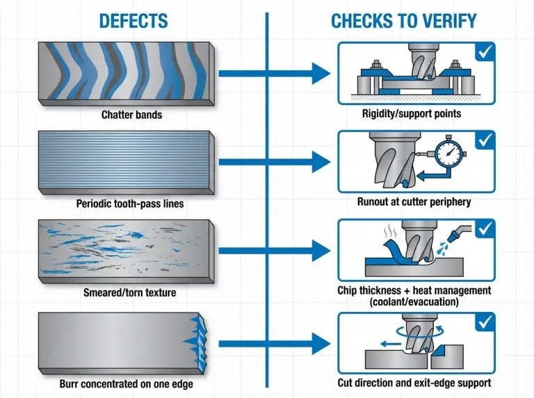
Diagnosing defects is faster when you map symptoms to likely causes. This prevents changing variables randomly. Change one stability lever at a time and confirm the effect.
|
Symptom |
Likely cause category |
First verification actions to take |
|---|---|---|
|
Chatter bands |
Stiffness margin or resonance |
Verify support/clamping, reduce overhang or engagement |
|
Periodic lines |
Runout or uneven tooth loading |
Check seating, measure runout, verify cutter condition |
|
Smeared texture |
Rubbing, built-up edge, or heat |
Verify chip thickness intent, coolant, and edge condition |
|
Burrs on one edge |
Exit-edge condition and cut direction |
Verify climb vs conventional, exit support, and feed |
|
Size drift or taper |
Workpiece movement or distortion |
Verify clamp distortion, support pattern, and datum |
Conclusion
At Yonglihao Machinery, we believe reliable results come from rigorous verification. We treat every plain milling operation as a repeatable, documented plan, tying cutter engagement, stiffness, and cut direction directly to your project’s specific requirements.
When we handle your custom cnc milling needs, our process is clear: we define parameters, verify runout, and validate stability with a test pass. If your part requires a flat surface to serve as a critical reference plane, we use our verification tables as a strict quality gate. By combining your drawing requirements with our setup constraints, we make plain milling predictable, precise, and high-quality as part of our cnc machining services for every prototype we manufacture.
FAQ
What is the Difference Between Plain Milling and Face Milling?
Plain milling cuts with the tool axis parallel to the surface. Face milling cuts with the axis perpendicular. Verify your choice against access, stability, and required texture. If you are unsure, state the engagement terms rather than just saying “facing.”
Is Plain Milling the Same as Slab Milling or Surface Milling?
Plain milling and slab milling usually describe the same operation. “Surface milling” can be ambiguous. Verify the correct meaning by stating cutter axis orientation. Make sure peripheral teeth are the primary cutting edges. Clear language prevents confusion during inspection.
When Should You Choose Climb vs Conventional in Plain Milling?
Choose climb milling when backlash risk is low and you need stable cutting. Choose conventional milling if backlash might pull the workpiece into the cutter. Verify your choice against machine condition, clamp direction, and exit-edge burr tolerance.
What Setup Checks Matter Most Before the First Pass?
Reliability depends on workpiece support and clamping stability across the full length. Next, check cutter mounting and runout. Runout drives surface marks and uneven loading. Use a controlled validation pass to confirm stability before you increase engagement.
What Usually Causes Chatter or Poor Surface Finish in Plain Milling?
Chatter usually means low stiffness, too much overhang, or bad engagement. Poor finish can come from runout, rubbing (low chip thickness), or heat. Fix it by verifying mounting and support first. Then adjust engagement and chip formation. Do not change many parameters at once.