
In manufacturing, shaft parts rarely have a simple structure with a single, uniform diameter. This often creates challenges in assembly, positioning, and functionality. For instance, components like bearings, gears, or seals usually require different diameters to fit properly. Step turning, an advanced method of external cylindrical turning, addresses these challenges. It enables the efficient creation of multi-segment diameter changes on a single workpiece. This helps manufacturers tackle the complexities of producing intricate parts.
This article will cover everything you need to know about step turning. We’ll explore its definition, purpose, process, challenges, and design optimization tips. By the end, engineers and operators will have practical guidance to boost production efficiency and reduce defects.
What is Step Turning?
Step turning is a machining process used to create cylindrical parts with multiple diameters. It works by segmentally reducing the diameter of a rotating workpiece. This process is also known as “step turning,” “stepped turning,” or “shoulder turning.” Its key features include the ability to create multi-diameter structures, shoulders (used for positioning), and transition zones with abrupt diameter changes.
Unlike straight turning, which keeps the diameter uniform along the workpiece, step turning introduces segmented diameter changes. This makes it ideal for manufacturing complex parts like shafts. These parts often need different diameters to fit bearings, gears, seals, or other components. By ensuring precise transitions between diameters, step turning meets the functional and structural demands of modern engineering. It’s a reliable solution for producing high-precision, multi-functional parts.
| Processing Goal | Geometric Form | Common Parts | Precision Challenges | Applicable Machine Tools |
|---|---|---|---|---|
| Step Turning | Multi-segment diameter changes | Segmented steps and shoulders | Step transition precision and coaxiality | CNC lathes |
| Straight Turning | Single uniform diameter | Straight cylinder | Overall straightness | Ordinary lathes |
What is the Purpose of Step Turning?
Step turning is used to create multi-functional diameter segments on a single shaft. This meets both assembly and structural needs.
Functional Purposes:
- Assembly Positions: Provides spaces for bearings, gears, pulleys, and other components, ensuring stable installation.
- Axial Positioning: The step shoulder acts as a reference point to prevent sliding.
- Sealing: Diameter differences create sealing positions for oil seals or O-rings.
- Fixing Elements: Snap ring grooves and nut segments with varying diameters help secure components.
Structural Purposes:
- Weight Reduction: Reduces the diameter of non-load-bearing segments to make parts lighter.
- Stress Optimization: Improves stress paths and enhances fatigue life.
- Cost Efficiency: Reduces material usage while improving overall part performance.
The Working Principle and Basic Logic of Step Turning
Step turning creates step diameter segments by combining Z-axis axial feed with X-axis radial cutting. The process follows a basic logic: roughing to finishing. This ensures gradual material removal for precision.
The typical sequence starts from the workpiece tail (end) and moves toward the chuck. This approach prioritizes processing smaller-diameter steps at the far end. It helps maintain material rigidity and minimizes deflection. The tool forms square or filleted shoulders by reaching specific positions, ensuring clear transition zones.
In practice, this logic maintains workpiece stability and prevents vibrations that could harm surface quality.
Types and Classifications of Step Turning
Step turning can be categorized based on structure, transition form, and processing method.
Classification by Step Structure
External Step Turning: This method is used for segmented changes in the external diameter of a workpiece. It is commonly applied in the external diameter processing of shaft parts. External step turning is ideal for handling multiple diameter changes efficiently. However, it requires tools with high rigidity to ensure precision.
Internal Step Turning / Stepped Boring: This approach targets segmented changes in the internal hole diameter of a workpiece. It is often used for precise processing of internal cavity steps, such as cylinder bore internal fits. It works well for multi-segment changes in internal diameters. During processing, proper coolant management is essential to maintain stability and extend tool life.
Classification by Transition Form
Square Shoulder / 90° Shoulder: This type features sharp, precise shoulder transitions. It is suitable for applications requiring accurate positioning, such as bearing seat processing. While it offers high precision, the sharp transitions can lead to stress concentration. Special care is needed in design and processing to avoid issues.
Filleted Shoulder: This method uses arc transitions to reduce stress concentration. It is ideal for parts that need improved fatigue resistance, such as drive shafts. The size of the fillet (R corner) must be carefully controlled to meet design specifications.
Chamfered Shoulder: Chamfered transitions make part assembly and positioning easier. This method is commonly used for processing assembly components. Consistency in chamfer size is critical for maintaining assembly precision. It is particularly useful in scenarios requiring quick and accurate assembly.
Classification by Processing Method
Traditional Manual Turning: This method is suitable for small-batch or simple step processing. It offers flexible operation and is ideal for non-standard parts or single-piece production. Although it is less efficient than modern methods, it remains indispensable in certain specialized scenarios.
CNC One-Time Clamping Continuous Step Processing: This approach completes multiple steps in a single clamping. It is highly efficient and precise, making it perfect for batch production and complex parts. CNC processing requires programming support, and optimizing the processing path is crucial for achieving high efficiency and quality.
| Type | Structural Features | Advantages | Typical Uses | Notes |
|---|---|---|---|---|
| External Steps | External diameter segmentation | Multi-segment changes | Shaft parts | High tool rigidity required |
| Internal Steps | Internal hole diameter changes | Precise internal fits | Cylinder bores | Coolant management needed |
| Square Steps | 90° transitions, sharp shoulders | Precise positioning | Bearing seats | Prone to stress concentration |
| Filleted Steps | Arc transitions, smooth shoulders | Fatigue resistance | Drive shafts | R corner control critical |
| CNC Continuous Processing | Automated path, one-time forming | High precision for batches | Complex shafts | Programming complexity |
How to Perform Step Turning?
The standard process for step turning includes clamping alignment, establishing benchmarks, rough turning, finish turning, detail processing, and inspection.
- Workpiece Clamping and Alignment: Secure the workpiece firmly to ensure it stays coaxial and avoids eccentricity. Misalignment can cause processing errors. For long shaft workpieces, use centers or steady rests to improve stability. Use dial indicators to calibrate and minimize runout during rotation.
- End Face Turning to Establish Benchmark: Turn the workpiece’s end face to make it flat and establish the Z=0 benchmark point. This point serves as a reference for measuring step positions, ensuring accuracy throughout the process.
- Measuring and Marking Step Positions: Use depth gauges or scribing tools to mark the length positions of each step. This ensures accurate dimensions during processing and avoids confusion.
- Rough Machining Steps: Start by rough turning the largest diameter step to remove most of the material. Leave a finish allowance of 0.2-0.5mm (unilateral). Then, rough turn the remaining steps in order, from large to small. Ensure each step has a reasonable finish allowance. Monitor for vibrations to maintain stability.
- Finish Machining Steps:Use low feed rates and high speeds for finish machining. Process the steps to their final diameter and length dimensions. Avoid stopping midway to prevent tool marks that could affect surface quality. This ensures a smooth finish and precise dimensions.
- Step Root Processing:Process the step roots based on design requirements. Perform undercutting, filleting, or chamfering to create smooth transitions. Use specialized tools to avoid burrs and reduce stress concentration. This improves the part’s fatigue strength.
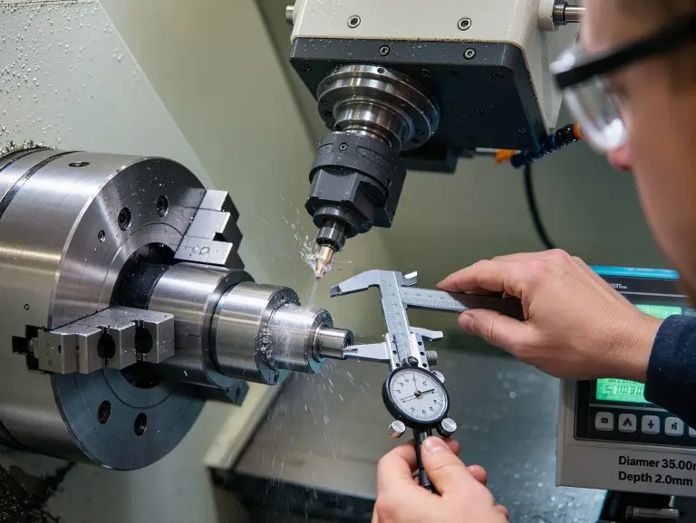
- Full Dimension Re-inspection and Coaxiality Inspection: Re-inspect the diameters and lengths of the steps using micrometers. Check the workpiece’s coaxiality and runout with runout gauges. Ensure all dimensions meet tolerance requirements and that coaxiality and runout are within acceptable ranges.
What Tools and Equipment Are Needed for Step Turning?
Step turning requires a variety of tools and equipment, divided into four main categories: machine tools, cutting tools, measuring tools, and support fixtures. Below is a detailed breakdown of each category and its functions:
Machine Tools
Machine tools are the core equipment for step turning. They include ordinary lathes and CNC turning centers.
- Ordinary Lathes: Suitable for simple step processing tasks. They are flexible and ideal for small-batch production.
- CNC Turning Centers: Support complex programming and automated processing. They can complete high-precision machining of multiple steps in one clamping. These are best for batch production and complex parts.
Choose the machine tool based on the complexity and precision requirements of the task.
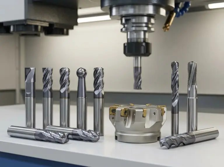
Cutting Tools
Cutting tools are essential for step turning. They directly affect the precision and surface quality of the steps. Below are the main types:
- External Turning Tool: Used for rough and finish machining of steps. It determines the diameter precision and surface quality. Regular sharpening is necessary to maintain sharpness.
- Grooving Tool: Used for machining undercuts at step roots. This ensures that parts like bearings fit fully against the shaft shoulder without interference.
- Radius Tool: Used for machining filleted steps. It ensures smooth transitions, reduces stress concentration, and improves fatigue resistance. Strict control of the fillet size (R corner) is required.
- Forming Tool: Used for processing special step shapes. It is suitable for steps with complex contours and often requires customization based on the workpiece.
Measuring Tools
Measuring tools ensure dimensional accuracy during processing. They are used for measurement and calibration:
- Vernier Caliper: Ideal for quick measurements of step lengths and diameters. It is simple to use and suitable for initial checks after rough machining.
- Outside Micrometer: Used for precise diameter measurements. It ensures dimensional tolerances are met. Always calibrate the zero point before use.
- Depth Gauge: Used to check step lengths and depths. It ensures accurate positioning during processing.
- Dial Indicator: Used to calibrate workpiece coaxiality and alignment. It reduces errors, especially for long shaft workpieces.
Support Fixtures
Support fixtures stabilize the workpiece during processing:
- Center: Fixes the end of the workpiece, ensuring stability. It is suitable for machining long shafts.
- Steady Rest: Supports long shafts, maintains coaxiality, and prevents bending. Adjust the clearance to avoid being too tight or too loose.
- Follower Rest: Reduces vibrations during machining. It is particularly useful for slender workpieces. Ensure smooth contact with the workpiece to avoid intensifying vibrations.
| Tool Name | Corresponding Process | Impact on Precision | Usage Notes |
|---|---|---|---|
| External Turning Tool | Rough/finish turning diameters | Directly determines surface quality | Regular sharpening |
| Grooving Tool | Undercut shoulders | Affects transition zone precision | Control depth of cut |
| Micrometer | Dimension inspection | Ensures tolerance compliance | Calibrate zero point |
| Steady Rest | Support long shafts | Maintains coaxiality | Adjust clearance |
By selecting and using these tools effectively, you can improve the precision and efficiency of step turning while ensuring safety and stability.
Key Process Parameters and Precision Control
The precision of step turning depends on three cutting elements, machine tool rigidity, clamping coaxiality, and tool compensation management. Below are the key parameters and optimization methods:
Three Cutting Elements
- Speed: Smaller diameters require higher speeds to maintain a constant surface speed (CSS). This ensures uniform cutting and prevents surface roughness or overheating.
- Feed: Use higher feed rates during rough turning to remove material quickly. Reduce the feed to 0.05-0.2mm/rev during finish turning for a smoother surface.
- Depth of Cut (DOC): During rough turning, use larger depths (2-4mm) to improve efficiency. For finish turning, keep the depth under 0.5mm to avoid tool deflection or vibration.
Tool Compensation and Coordinate Management
In CNC machining, tool nose radius compensation is critical for accurate step lengths and chamfers. Ensure tool compensation parameters align with the coordinate zero point to avoid errors. Regularly check and adjust tool compensation values to account for wear.
Error Sources and Countermeasures
- Tailstock/Center Misalignment: This can cause taper errors. Use laser alignment tools or dial indicators to correct coaxiality.
- Tool Dwell: Stopping midway leaves tool marks. Use continuous machining or slightly overlap cutting paths to eliminate marks.
- Tool Wear/Thermal Deformation: These can cause diameter drift. Monitor tool condition and replace or sharpen tools as needed.
Tolerance Control
By optimizing cutting parameters, machine settings, and tool compensation, tolerances can typically be controlled within ±0.01mm. For extremely high precision (±0.005mm), use advanced hard turning or grinding processes.
Common Defects, Causes, and Solutions
Below are the manifestations, main causes, and quick countermeasures for common defects in step turning:
| Defect Manifestation | Main Cause | Quick Countermeasure |
|---|---|---|
| Dimensional Deviation | Tool wear or compensation error | Regularly check tool condition and adjust tool offset promptly. |
| Surface Roughness | Excessive feed or poor cooling | Reduce feed rate and increase coolant supply. |
| Taper Error | Misaligned tailstock/center | Use a dial indicator to calibrate coaxiality. |
| Tool Marks | Midway stopping or uneven paths | Use continuous machining or overlap cutting paths slightly. |
By setting proper parameters, managing tools effectively, and adjusting strategies as needed, you can reduce defects and improve the precision and surface quality of step turning.
Advantages of Step Turning
Step turning is an efficient and precise machining method with several key advantages:
- One-Time Clamping for Multi-Diameter Segments: Step turning allows multiple diameter segments to be completed in one clamping. This eliminates cumulative errors caused by repeated clamping. It ensures the coaxiality of all steps within 0.01mm, significantly improving precision while reducing clamping time.
- High Production Efficiency: By reducing clamping and tool setup time, step turning can save 20-30% of the processing cycle in batch production. In CNC turning centers, automated processing paths further enhance efficiency, making it ideal for large-scale production.
- Handling Complex Step Contours: CNC step turning easily handles complex step contours, such as multi-level variable diameter shafts or designs with chamfers and fillets. Programming and automated control improve both precision and flexibility, making the process highly adaptable.
- Consistent and Controllable Surface Quality: Step turning achieves Ra0.4-0.8 mirror finishes through fine adjustments to parameters like feed rate, speed, and depth of cut. This ensures consistent surface quality, which is critical for parts like automotive drive shafts and precision mechanical components.
- Reduced Costs in Batch Production: In batch production, step turning minimizes auxiliary operations like multiple clamping and tool setup. It also reduces scrap rates, lowering overall production costs. For large-batch processing, this method delivers significant economic benefits.
- Enhanced Competitiveness in Practical Applications: Step turning is particularly advantageous in producing automotive shafts, drive shafts, and similar parts. Its high-precision and high-efficiency methods improve product quality and production speed, helping manufacturers gain a competitive edge in the market.
Through these advantages, step turning meets the demands for high precision and efficiency. It also offers significant cost-effectiveness and reliability, making it indispensable in modern manufacturing.
Challenges and Countermeasures of Step Turning
Despite its advantages, step turning faces several challenges in actual processing. These include material waste, tool rigidity, stress concentration, and thermal deformation. Below are the common difficulties and their solutions:
- Material Waste: Step turning removes excess material starting from the largest diameter, which can lead to significant waste. Using near-net-shape blanks, such as forgings, helps reduce the initial material volume and overall costs.
- Insufficient Tool Rigidity for Deep Steps: Excessive tool overhang during step turning can result in chatter, causing surface defects. Short shank tools and adjusted cutting parameters are effective in minimizing vibration and improving surface quality.
- Stress Concentration at Square Roots: Square step roots are naturally prone to stress concentration, increasing the risk of fatigue fractures. Incorporating fillets or undercuts in the design enhances part durability and reduces the likelihood of failure.
- Thermal Bending of Slender Shafts: Cutting heat generated during step turning can accumulate, leading to thermal bending in slender shafts. Strengthened coolant use and additional support, such as steady rests, ensure stability throughout the process.
By optimizing processes and designs, these challenges can be effectively managed, ensuring reliable and high-quality results.
Applicable Materials (Materials)
Step turning works with almost all turnable materials. However, processing characteristics and tool selection must match the material to ensure efficiency and quality. Below are common materials and their processing notes:
| Material | Processing Characteristics | Tool Suggestions | Typical Problems |
|---|---|---|---|
| Carbon Steel | High toughness, easy to cut but prone to rust | High-speed steel tools | Oxidation issues |
| Stainless Steel | Corrosion-resistant but prone to work hardening | Coated carbide tools | Tool sticking, tool wear |
| Aluminum Alloy | Lightweight, low cutting force, easy to finish | Sharp edge tools | Burr issues |
| Titanium Alloy | High strength, low thermal conductivity, heat-prone | Sharp fine-grain carbide tools (PVD coated) | Thermal deformation |
| POM Plastic | Wear-resistant, low friction, suitable for light loads | Standard turning tools | Melting due to high temperature |
Processing Tips:
- For stainless steel, use low speeds and high feeds with sufficient cooling.
- For aluminum alloys, apply lubricants to prevent sticking.
- For titanium alloys, control cutting heat to avoid thermal deformation.
Application Fields and Typical Parts
Step turning is widely used in industries requiring multi-segment diameters and high-precision fits. Below are its main applications and typical parts:
- Automotive Industry: Used for drive shafts, camshafts, and half shafts. These parts require multi-segment diameters to support bearings and gears, ensuring smooth power transmission.
- Aerospace: Applied to turbine shafts and landing gear struts. These parts provide high-strength positioning surfaces to withstand extreme loads.
- General Machinery: Used for motor rotor shafts and machine tool spindles. Step turning ensures precise fits for these components.
- Energy/Oil and Gas Industry: Used for valve stems and drill tool shaft segments. These parts handle high-pressure and corrosive environments.
Parts often include multiple assembly positions on one shaft. Key segments have tight tolerances (e.g., ±0.005mm) to ensure functionality, while non-key segments have looser tolerances to simplify processing.
Step Turning vs Other Turning Methods
The main difference between step turning and other turning methods lies in the “diameter change method” and “target geometry.” Below is a comparison:
| Process | Diameter Change Form | Typical Parts | Advantages | Limitations |
|---|---|---|---|---|
| Step Turning | Abrupt segmentation | Drive shafts | High coaxiality, multi-segment diameters | Prone to vibration in deep steps |
| Taper Turning | Gradual slope | Tool handles | Smooth transitions, tapered parts | Precision depends on angle control |
| Copy Turning | Curve contours | Irregular shafts | Flexible shaping, complex profiles | Programming complexity, lower efficiency |
| Milling | Non-rotating cutting | Flat steps | Multi-axis processing, high flexibility | Lower coaxiality, unsuitable for shafts |
For example, step turning excels in precision and coaxiality for shaft parts compared to milling. However, it offers less flexibility. Taper turning is better for gradual transitions, such as tool handles. Choosing the right method depends on the part’s geometry and processing needs.
Engineer Guide: Design and Processing Optimization Suggestions
A well-designed step shaft can reduce machining difficulty and costs. Follow these tips:
- Avoid Sharp Internal Corners: Add R corners or undercuts (e.g., R0.5-1mm) to reduce stress concentration and improve fatigue life.
- Tolerance Allocation: Use tight tolerances for key segments (e.g., ±0.01mm for assembly positions) and loose tolerances for non-key segments (e.g., ±0.1mm for transitions).
- Processing Sequence: For slender shafts, process from the tailstock toward the chuck to avoid deflection.
- Blank Selection: Use forged or cast near-net-shape blanks for batch production. This reduces material removal by 20-30%.
- Length-to-Diameter Ratio >10:1: Use steady rests or follower rests to maintain stability.
- Shoulder Forms: Confirm shoulder designs during the design stage to ensure manufacturability and simulate potential defects.
Conclusion
As a company focused on prototype manufacturing, Yonglihao Machinery deeply understands the importance of step turning in modern manufacturing. It is not only an efficient processing method but also a key process for solving production challenges of complex shaft parts. Through reasonable design optimization and precise processing control, we can help customers achieve high coaxiality and multi-functional assembly part needs, while significantly improving production efficiency and reducing costs.
At Yonglihao, our CNC workshop services are centered on precision and reliability, combined with rich processing experience and advanced equipment, capable of handling CNC turning machining tasks from simple to complex. Whether it’s drive shafts, turbine shafts, or high-precision custom parts, we are committed to providing high-quality solutions for customers. Through optimized design, precise processing, and strict inspection, we not only help customers solve manufacturing challenges but also provide strong support for their product performance and market competitiveness.
If you are looking for professional CNC processing services or need to optimize your part designs, welcome to contact Yonglihao. We look forward to cooperating with you to jointly promote innovation and development in manufacturing!
FAQ
What is the Highest Precision Step Turning Can Achieve?
Under standard CNC conditions, step turning can achieve tolerances of ±0.01mm. With high-end machines and strict environmental control, it can reach ±0.005mm. For even higher precision, grinding is recommended.
How to Avoid Tool Marks at Steps?
Use continuous finish machining paths and avoid stopping midway. Apply tool nose compensation and slightly overlap cutting paths to achieve surface roughness below Ra0.4.
Why Do Step Diameters Turn Out Tapered?
This is often caused by clamping misalignment or thermal deformation. Use dial indicators to calibrate centers and strengthen coolant to control temperature changes.
How to Choose Between Square Steps and Filleted Steps?
Square steps are ideal for precise positioning but can cause stress concentration. Filleted steps are better for high-load parts to improve durability. Choose based on fatigue analysis.
What Typical Parts is Step Turning Suitable For?
Step turning is ideal for shaft parts like drive shafts, valve stems, and rotor shafts. These parts require multi-segment diameters for assembly and functionality.