


Die casting mold decides part quality before metal enters the cavity. The mold controls flow, air removal, heat balance, and ejection. A good mold creates stable parts, clean surfaces, and few defects. It also ensures a predictable cycle time. This guide covers the mold itself. We will look at what it is, its parts, and its design process. We will also cover how to choose the right mold for your project.
What Is a Die Casting Mold?
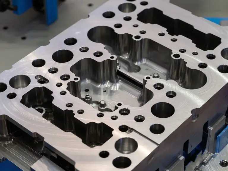
A die casting mold is a tool made of hardened steel. It forms molten metal into a near-net-shape part using high pressure. The mold has two halves. One is the fixed (stationary) half. The other is the moving (ejector) half. They close to form the part cavity and open to release the casting.
A die casting mold is more than just a cavity. It is a system that controls metal flow, trapped gas, and temperature. It also manages the part’s release. This allows the same part shape to be made for thousands or even millions of cycles.
Key Systems and Components Inside a Die Casting Mold
A die casting mold has many systems. They work together to fill, cool, and eject the part with consistency. If one system is weak, defects often appear. This can happen even if the cavity shape is correct. Gating, venting, and cooling are especially important.
- Cavity & Core: The cavity forms the part’s outer surfaces. The core forms internal features. These include holes, recesses, and pockets. The draft and surface finish in these areas affect ejection marks and part stability. They can also cause the part to stick.
- Fixed Die & Moving Die: The fixed half connects to the machine’s injection side. It often contains the entry point for the metal, called the sprue. The moving half usually holds the cores and the ejection system. This design helps the casting stay on the moving side for a clean release.
- Gating System: The gating system acts like traffic control for molten metal. The sprue feeds the runner, and the runner feeds the gate. The gate controls how the cavity fills. The gate’s location and thickness affect the fill pattern and weld lines. It also influences how fast the gate freezes, which impacts pressure and porosity.
- Venting & Overflow: Venting gives trapped air and gases an escape path as the cavity fills. Overflows help capture the first metal, oxides, and gas. This happens at the end of the fill. Poor venting is a common cause of gas porosity, burns, and incomplete parts (short shots).
- Cooling Channels: Cooling channels remove heat from the die steel. This helps stabilize the mold’s temperature. A good layout reduces hot spots, warping, and the risk of metal sticking (soldering). It also leads to a more consistent cycle time.
- Ejection System: Ejector pins, sleeves, and plates remove the casting without bending it. Pins should be placed to avoid weak ribs, thin walls, and cosmetic surfaces.
- Slides/Core Pulls: Slides and core pulls create undercuts and side features. These features cannot be formed by the straight opening of the die. Slides add capability, but they also create wear points. They can be sensitive to heat and require more maintenance.
Main Types of Die Casting Molds
Cold-Chamber Die Casting Mold
This mold is for machines where metal is ladled into a shot sleeve before injection. It is a common choice for aluminum and many magnesium parts. It works well for medium-to-large castings. It suits alloys with higher melting points and allows for larger shot sizes. However, it usually runs slower than hot-chamber molds. It is also more sensitive to temperature control and clean metal.
Hot-Chamber Die Casting Mold
This mold works with machines where the injection system is in the molten metal. This allows for very fast cycles. It is often used for zinc and small, complex parts that need high production rates. It offers short cycle times. But, it is not a good fit for most aluminum due to the high melt temperature. This can cause corrosion in the injection system.
Single-Cavity Mold
A single-cavity mold makes one part per shot. It is often the best choice for large castings or new projects. It makes it easier to balance the flow, venting, and temperature. This is simpler than in molds with multiple cavities. Its output per cycle is lower, so the cost per part may be higher for large volumes.
Multi-Cavity Mold
A multi-cavity mold makes several identical parts in one shot. This increases output without adding to the cycle count. It is best for stable parts with high demand. It is also good when the process is already proven. This design demands good runner balance and consistent venting. Poor balance often causes differences between cavities and creates scrap parts.
Prototype / Rapid Tooling Die
A prototype die focuses on speed and cost. It helps confirm a part’s shape, fit, and function quickly. These tools may use simpler cooling, ejection, and standard parts. They are great for design checks and small production runs. However, they usually have a shorter life. They may not match a full production tool in surface finish or cycle stability.
Production Die
A production die is built for stable, high-volume work. It has optimized gating, cooling, and venting. It also has features to protect against wear. The tool steel (often H13-class for aluminum) and heat treatment are key to a long life. This tool takes longer to build and costs more upfront. But it saves money through less scrap, shorter cycles, and fewer stops.
Unit / Insert-Based Die
A unit die uses swappable cavity blocks within a standard holder. It is useful for part families, design changes, or parts that share a common tool structure. This approach improves flexibility. However, you must control the fit, heat expansion, and alignment of the inserts. This helps avoid flash and part mismatch.
Trim Die
A trim die is a second tool used after casting. It removes the runner, gate marks, and flash. It is more efficient and consistent than trimming by hand, especially at high volumes. It does not fix problems from the casting process. If flash is bad due to die wear or poor fit, you must fix the cause in the casting die.
|
Mold Type |
Best for |
Watch-outs |
|---|---|---|
|
Cold chamber |
Aluminum / bigger parts |
Thermal control, venting discipline |
|
Hot chamber |
Zinc / small complex parts |
Alloy limits, corrosion issues |
|
Single-cavity |
Large parts / stable quality |
Lower output per cycle |
|
Multi-cavity |
High volume |
Balance, cavity-to-cavity variation |
|
Prototype/rapid |
Validation |
Shorter life, simple cooling/ejection |
|
Production |
Mass production |
Higher lead time and cost |
|
Unit/insert |
Part families |
Insert alignment and wear |
|
Trim die |
Post-cast trimming |
Won’t solve root-cause flash |
Step-by-Step Die Casting Mold Design Workflow
A good mold design follows a clear workflow. It first ensures the part can be made. Then it builds the flow, venting, cooling, and ejection systems around it. Skipping early DFM, parting line, and release decisions often leads to rework later.
First, start with part requirements. This includes alloy, surface finish, tolerance, and volume. Then, define the parting line and the die-opening direction. Confirm the draft angles and wall thickness strategy. Next, design the gating and runner layout. Then, plan the venting and overflow positions. This ensures a complete fill without trapping air.
Finally, build the cooling plan to balance heat. Then, finalize the ejection and slide actions. This ensures the casting releases without damage. CAE simulation is very useful here. It can check the fill pattern, air trap risks, and hot spots before cutting any steel.
Key Design Rules That Decide Part Quality
The best way to get good results is to link design rules to the defects they prevent. If you cannot explain what defect a feature prevents, the design may be unclear.
Practical checklist (use during design review):
- Draft & release: Use enough draft where the part grips the die. This reduces sticking and drag marks.
- Wall thickness: Avoid sudden thick-to-thin changes. This reduces shrinkage, porosity, and warping.
- Gate placement: Feed thick sections first. Control how flow fronts join. This reduces cold shuts and weak weld lines.
- Venting: Place vents where the flow ends, not where it starts. This reduces gas porosity and burns.
- Heat balance: Cool hot zones on purpose. Don’t over-cool thin cosmetic walls. This reduces warping and soldering.
- Ejector layout: Support ribs and bosses during ejection. Avoid cosmetic faces. This reduces pin marks and bending.
|
Symptom |
Mold-side check first |
|---|---|
|
Gas porosity / blow holes |
Vent/overflow location & capacity, gate turbulence |
|
Cold shut / short shot |
Gate size/location, runner balance, end-of-fill venting |
|
Flash |
Parting-line fit, alignment, insert support, local die wear |
|
Warpage |
Cooling balance, hot spot management, ejection distortion |
|
Sticking / soldering |
Surface condition, thermal hot spots, release strategy |
How Die Casting Molds Are Manufactured and Approved?
A die casting mold is made through a controlled process. This includes machining, heat treatment, fitting, and tryouts. Consistency comes from how well the tool is built and tested, not just the CAD model.
A common build path starts with preparing the tool steel. It then moves to rough CNC machining and precision finishing. EDM is used for fine details. Heat treatment gives the steel hardness and fatigue resistance. This is followed by surface finishing, like polishing, for better release and wear.
Verification is important at every stage. Dimensional checks confirm key geometry. Assembly checks ensure proper alignment and clearance. The first-shot tryout is a learning cycle. It involves tuning gates, vents, and cooling until the tool makes stable parts.
Conclusion
At Yonglihao Machinery, as a dedicated die casting manufacturer, we understand that a high-performing die casting mold works as a coordinated system. Our expertise ensures that geometry shapes your part, gating fills it, venting protects it, cooling stabilizes it, and ejection releases it—each with precision. By designing every system to prevent defects, we help our clients achieve consistent quality, predictable cycle times, and extended tool life with our professional die casting services.
What is the typical lead time to produce a die casting mold?
Lead time depends on complexity and testing. It can range from weeks to months. More slides, tight tolerances, and high cosmetic needs usually add time. This is due to extra fitting and tryout steps.
How do I choose between a cold-chamber and a hot-chamber mold?
Choose based on alloy and part size first. Cold-chamber is the practical choice for most aluminum parts and larger castings. Hot-chamber is common for zinc and small parts needing very fast cycles.
Why are venting and overflow design so critical?
The cavity must fill while air escapes, not as air gets trapped. If air cannot get out at the end of the fill, you will have problems. You will fight porosity, burns, and short shots, even at high pressures.
Do I really need uniform wall thickness for die casting?
Yes, uniformity is a key driver of stability and low scrap. Large jumps in thickness create hot spots and shrinkage. This can turn into porosity, distortion, and inconsistent part dimensions.
Can one mold support multiple production runs or revisions?
Yes, if it’s designed for easy maintenance and changes. Inserts, replaceable wear parts, and regular inspection help the tool stay repeatable. But major part changes may require a new cavity or insert.


