

The demand for customized products has been increasing due to the growth of society, which prompted people to conduct research. Eventually, they proved that sheet metal is a versatile material that can be machined into various shapes. This transformation is accomplished through the use of simple sheet metal forming processes, such as metal bending. It is possible to mold sheet metal into the shapes required for various production purposes.
Numerous processes are involved in achieving this. and learning how to bend sheet metal requires a basic understanding of them. This article will discuss the significance of sheet metal bending, its role in sheet metal fabrication processes, and how to bend sheet metal. In addition, it also provides some essential tips that can help you bend steel plates.
What is Metal Bending?
Did you know that most sheet metal parts are created by first cutting to certain sizes, then bending to the correct shape, and then assembling? As a result, it plays an important role in sheet metal fabrication.
Sheet metal bending deforms a flat metal sheet into a certain angle or curve. The sheet’s thickness remains unchanged. Instead, the final shape is formed as a result of permanent plastic deformation. Typically, a press brake or similar equipment device applies pressure along a straight axis to bend the metal to the desired angle.
To grasp the core principle, you must first understand the punch-and-die configuration. A punch uses force to distort metal against a die. Meanwhile, the die supports and forms the metal to the appropriate bend angle and radius.
How Does Metal Bending Work?
Step 1: Initial Design
The metal bending process begins with the production of a thorough design for the finished part. CNC bending requires 3D files, which you can create using applications like AutoCAD and Solidworks. As a result, the design must take into account a range of factors, such as allowance, reliefs, springback, and so on.
You can use an online bending calculator to determine design factors and considerations. In addition, you must provide accurate measurements and tolerances in the design.
Step 2: Prepare Your File
Ensure that your file is in the appropriate format and that all GD&Ts are manufactured. Next, the bend line indicator is an important tool for discussing the design between engineers and technicians. It may be represented by many symbols depending on the software and file type, solid, dashed center lines, or even separate colors.
Step 3: The Bending Process
Sheet metal is bent along a straight axis to achieve the desired angle or curvature. Arrange the tooling (ddies punches, and press brakes) according to your needs and the specified angle. This method produces complicated pieces but has limitations: no angles greater than 130°. As a result, the bend radius varies with material and thickness.
Step 4: Finishing Processes
Sheet metal processes leave various aesthetic imperfections on the surface, such as die marks and uneven texture. To improve this, employ an appropriate surface finishing procedure. Examples include painting, powder coating, sandblasting, plating, and so on. However, if the surface has no effect on performance and aesthetics are not important to you, you can leave it as is.
Types of Metal Bending Processes
Sheet metal bending processes are similar in that the ultimate goal is to change metal structures into the required shapes. However, they operate differently. Understanding how to bend sheet metal requires knowledge of the material thickness, bend size, and bend radius. In addition, the intended use of the part will affect the method used.
The method outlined here will show you how to bend sheet metal. In addition, it will help you choose the proper strategy to get the best results. The most often used sheet metal bending processes are:
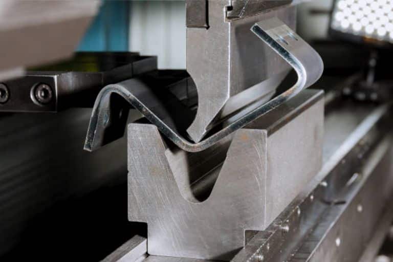
V-bending
This is the most often used sheet bending method. It uses a punch and v-die to bend sheet metal at the desired angles. Throughout the process, the bending punch presses against the sheet metal put over the V-die.
The angle generated by the sheet metal depends on the pressure point of the punch. This makes the procedure simple and efficient because it can be used to bend steel plates without changing their position.

There are three types of V-bending methods:
Bottoming
Bottoming is similar to air bending, except that the punch forces the sheet into the die until it completely hits the hollow surface. This process corrects the spring back risk flaw associated with the air method.
In addition, priming requires the use of a heavier punch as it increases the force of deformation. Importantly, it also holds the sheet for a short period of time after the process is complete. In addition, It is compatible with the V and V dies.
Furthermore, this procedure is more exact, as it does not require precise control over tonnage, unlike other processes. As a result, antiquated and inaccurate punches and press brakes can also be used to execute bottoming.

Coining
Coining is the process of squeezing a sheet between a punch and a die under high pressure. As a result, deformation yields precise bending angles with minimal spring-back effects.
Despite the accuracy of embossing, embossing requires greater tonnage. In addition, the cycle time for this process is longer than other processes.

Air Bending
Air bending, or partial bending, is a less accurate process than bottoming and coining. However, it is commonly used because of its simplicity and ease of manipulation. Because it does not require any instruments. However, air bending is what may cause the sheet metal to spring back.
In air bending, the punch applies force to the sheet metal that is sitting on both points of the die’s aperture. A press brake is frequently used during V bending so that the sheet metal does not come into touch with the bottom of the die.

Roll Bending
Roll bending is a method that shapes metal sheets into desired curves using two, three, or four rollers. The most typical design is the 3 roller configuration, where the three rollers are arranged in a triangular pattern. The upper roller is adjustable, while the other two are permanent.
The metal sheet is guided between the upper roller and the two fixed rollers. As the two fixed rollers rotate, they grasp the sheet, while the adjustable roller applies downward pressure to obtain the desired curve. The 4-roll arrangement includes an extra roller for further support, making it perfect for heavy-duty applications.
This process is commonly used in sheet metal fabrication to create cylindrical and conical. Structures such as tubes, cylinders, tanks, pressure vessels, and pipes.

Wipe Bending
Wipe or edge bending uses a wiping die and punch. The sheet is clamped between the die and a holding pad, revealing the section that will be bent. The punch or wiping flange then descends, pushing the edge of the part to the appropriate angle. This procedure is a great alternative to employing a press brake for smaller profiles.
This approach allows all sides of the edge to be molded at the same time, which considerably increases output. Additionally, the probability of surface cracking in the distorted area is low.

Rotary Bending
It is more common for tubes and pipes to have curvatures ranging from 1 to 180 degrees. However, it does not only apply to bent sheet metal. The procedure utilized a bend die, a clamp die, and a pressure die. The bend and clamp die to hold the work in place, while the pressure die provides tangential pressure to the reference position from the free end. Here, the rotary die can be rotated to the required position and radius. In addition, a “mandrel” is put inside the tube or pipe, which is not required for sheet metal construction.
This metal-forming procedure is appropriate for producing curve shapes from flat sheets. Meanwhile, it finds several uses in tube shaping. You gain more control over the process and can keep an accurate and precise radius. It can easily reach a tolerance of ± 0.5°. Therefore, since the tonnage required is 50% to 80% or less. Metal surfaces are therefore less prone to cracking and other problems.

Materials that Can Be Used for Metal Bending
There are different types of metals and alloys that are suitable for bending processes. However, the mass of each material type determines variables such as tonnage and rebound. As a result, the wide range of material possibilities allows you to select the greatest fit for the desired functionality and performance.
Furthermore, the maximum thickness of metal sheets that can be manufactured varies according to the material used. Aluminum, for example, is more formable than titanium and can be molded into thicker sheets.
Stainless Steel
Stainless steel is a versatile material with high strength, hardness, and corrosion resistance. In addition, it is ideal for molding small-radius parts. Various grades, including 304, 316, and 430 stainless steel, are widely utilized. Because of its hardness, shaping stainless steel requires more pressure and the spring-back effect must be carefully considered to assure accuracy.
Steel
Steel alloy grades such as A36, 1018, and 4140 are widely used in metal bending due to their high tensile strength, durability, cost-effectiveness, and adaptability. While steel may require heat treatment for more complex processes, it remains easier to work with than stainless steel. In addition, mild steel is particularly easy to form.
Aluminum
Aluminum is ductile and easily formed into a variety of shapes and curves. It has superior corrosion resistance and strength-to-weight ratio. Aluminum bent parts are commonly utilized in aerospace, automotive, and electronics. However, it may be subject to breaking, particularly with smaller radii.
Brass
Brass is malleable and conductive, and it bends more easily than steel. Various grades, such as CZ129/CW611N, are routinely used to make sheet metal. Brass is commonly used in electrical, thermal, and plumbing applications due to its ease of forming and good conductivity.
Copper
Copper is a soft substance, and sheets are easily bent. However, to avoid surface damage or cracking, it must be handled carefully and with controlled force. Furthermore, copper’s glossy appearance makes it popular in electrical and other applications.
Key Concepts of Sheet Metal Bending
Different concepts can be found in sheet metal bending. Such as design considerations to incorporate into the dimensions after the procedure. Before we get into the key topic, let’s go over some relevant terminology.
- Neutral Axis: The neutral axis is an imaginary line in sheet metal that does not stretch or compress while exerting force.
- Tension Zone: The tension zone is the area on the outside of the bend where the metal stretches.
- Compression Zone: The compression zone is the area on the inside of the bend where the metal compresses.
- Bend Line: The area where the sheet metal is bent.
- Flange Length: The length of the straight and flat part that extends from the bend.
The important concepts are as follows.
Bend Radius
It is the radius of the bent sheet metal formed by bending sheet metal. All designs begin with this critical variable. It has a considerable impact on dimensional accuracy, final strength, shape, and structural integrity.
This radius has a minimal value that is determined by the material type and thickness. It means that you cannot bend sheet metal with a very small radius, there is a limit. Typically, the radius must be more than or equal to the thickness of the sheet.
Minimum Bend Radius(Rmin)= Thickness(t).

Bend Deduction
The total length of the flat segment is slightly reduced after the operations since the bent portion strains some material. Therefore, to calculate the overall flat length, deduct some length, which is known as the bend deduction. So, it refers to the amount of material that must be reduced from the overall length of flat sheet metal in order to reach the necessary measurements. It means you have to subtract a length to get the proper flat length.
Bend Deduction = 2x (Outside Setback – Bend Allowance)
Consideration of deduction in design is critical to ensuring the correct length and other parameters of pieces. Furthermore, sheet metal gauges (thickness), radius, and material type influence the deduction amount.

Bend Allowance
Bend allowance is a manufacturing phrase that refers to the space allocated to accommodate sheet metal stretch and bending. When sheet metal is modified from its original flat shape, its physical dimensions change. The force used in the work causes the material to compress and stretch both inside and outside.
This deformation alters the overall length of the sheet metal as a result of the compression and stretching forces applied to the bend. However, the length computed from the thickness of the inner compressed surface and the exterior under stress remains constant. This is represented by the “neutral axis.”
The margin takes into account the thickness of the sheet metal, the angle, the method used, and the K-factor. The K-factor is usually used to estimate the constant of material stretching. It represents the ratio of compression on the inside to tension on the outside of the bend.
The inner surface of the sheet metal compresses, while the outer expands. As a result, bending sheet metal does not change the K factor. The K-factor (typically between 0.25 and 0.5 max) is used as a control figure in design variable calculations. It helps to determine the exact material needed before trimming a sheet metal section. In addition, it is useful in charting the bending radius of sheet metal.
K-Factor
It’s another important feature of sheet metal bending design. The k-factor characterizes various bent sheet metal geometries and aids in the calculation of other design parameters such as needed allowance. The K-factor is defined as the “ratio of length that the neutral axis shifted from the original position to sheet thickness.” Its value ranges from 0 to 1. For example, 0.2 indicates that the neutral axis will be displaced by 20% of the thickness. In addition, the suggested value varies depending on the material type and bend radius.
K factor also indicates how the material stretched and expanded inside and outside of the bend. Therefore, it is critical to compute the flat length-related design parameters.

Bend Relief
Relief is a minor incision at the end of a bend line that prevents material distortion and ripping. It is critical for the structural integrity and precision of finished parts and products. You can make notches, holes, and cutouts.
You do not need to consider it for a straight curve from one edge to the next. Only examine whether they must separate from flat material other than the edges. The reason for this is that if there is immediate material following the compressed material, you must adjust the flat material.
The rule of calculating:
The minimum width and depth of the relief are equal to thickness(t)/2 and thickness(t) + bend radius(R) + 0.5 mm, respectively.
Another comparable notion is corner relief. Which is the length that must be taken out at the meeting point of the bent line. So, at the corners, you should consider a cut-out to ensure proper alignment and prevent material tearing.
Springback
The final shape of the metal plate will usually be different after the force is applied and released. It may contract after you bend the metals into a precise curve of shape, compromising dimensional accuracy. As a result, the designs require some adjustments to spring back for precision.
To comprehend this phenomenon, one must first understand the concepts of permanent and elastic deformations. Elastic deformations attempt to maintain their shape, whereas permanent deformations keep the deformed shape constant. Some elastically deformed material around the bending line attempts to return to its former shape, resulting in spring back. The springback is also affected by factors such as the process used, the radius, and the material qualities.
Bend Sequence
It is a methodical approach of creating several bents in a single sheet with no interference or distortion. Bend sequence includes sorting them according to their size and intricacy. The conventional order begins large and simple and gradually becomes more intricate. The sequencing is also relevant to the die and tooling. It must be achievable with the appropriate tooling (dies and press brake).

Grain Direction
Internally, all metallic formations are crystalline lattices, which are repetitively arranged atomic structures. As a result, grains are unique crystalline areas within the metal. The orientation and shape of these grains might vary according to the material and method of formation (forging, casting, etc.).
Consider the grain direction during press braking at tighter angles or curvatures to lessen the fracture risk. Meanwhile, the grain direction should be perpendicular to the bend to avoid cracking.
Practical Guidelines for Designing Sheet Metal Bending Parts
Sometimes a simple oversight or error in sheet metal design might cause problems with bent sheet metal. As a result, every feature and detail has an impact on the overall quality of the final product. Here are some practical design tips:
Maintain Uniform Thickness
The worksheet’s thickness must be consistent throughout the cross-section. Otherwise, it produces an uneven bend radius and increases the likelihood of cracking or warping. Typically, you can select a consistent thickness of 0.5 to 6mm.
Bend Radius and Orientation
The minimum bend radius is limited and varies depending on the material type and thickness. “The minimum radius should be at least equal to the sheet thickness” is a typical rule of thumb. Maintain a consistent radius along the bent line while keeping them in the same plane.
Avoid Successive Bends
Designing bends too close together might lead to alignment concerns and increased residual stress. As a result, a suitable space between them is required, at least three times the thickness. This prevents problems with bent metal parts.
Use Bend Relief
If the bends are near the end, it may tear or shatter owing to severe force. To avoid this, employ reliefs, such as minor cuts and notches, at the beginning and end of the line.
Proper Hole and Slot Placement
If your design incorporates holes and slots, you must be careful about their location. Such as including size and distance from the bend. This is because too close holes to the curvature line can result in material distortion. T represents sheet thickness and R denotes bending radius.
- The minimum distance (bend to hole) is equal to 2.5 t plus R
- Minimum distance (slot to hole) = 4t + R
- Minimum distance (edge-to-hole) = 3t
- The minimum hole radius (r min.) equals 0.5 t
Countersink Design
These features can be accomplished through machining or punching with a press brake. There are various guidelines governing their placement in designs:
- Maximum depth equals 0.6 t
- Minimum distance from the bend: 3t
- Minimum distance from the edge: 4t
- Distance between two countersinks equals 8t
Correct Curl Dimensions
Curl means bending a circular roll (hollow) at the edge of a metal sheet. It is used to retain edge strength while avoiding sharpness. Consider the following factors while building a curl feature:
- The minimum outer radius equals 2t
- The minimum distance (bend to curl) is equal to curl radius + 6t
- The minimum distance (hole to curl) is equal to two times the curl radius plus t
- Finally, there’s no crossover between curl and other features
Designing Hems
Hems are folded-back edges of sheet metal pieces that can open and close. Sometimes connecting two hems serves as a fastener. Bend sheet metal while meeting the following criteria:
- The minimum inside radius equals 0.5 t
- Minimum return length for the closed hem: 4t
- Minimum return length for the open hem: 4t
- From the inside edge of the bend to the outside edge of the hem, use the formula 5t + hem radius.
Flange and Chamfer Design
A flange is an edge that extends from the main body of a sheet metal item, usually at 90°. If you have flanges in your design, consider the following dimensioning limits:
- Minimum flange length equals 4t
- Minimum bend radius equals t
- Minimum bend-to-flange distance equals 2t
Tabs and Notches
The most common sheet metal features used for connecting are tabs and notches. A tab is a little extension of the edge, whereas a notch is a small cutout. They have the potential to weaken the material if not positioned correctly. Consider the following design rules:
- Minimum bend-to-notch distance equals 3t + radius (R)
- Minimal distance between notches: 3.18 mm.
- Minimum notch length equals 2t
- The minimum notch width equals 1.5 t
- Maximum tab and notch length equals 5 times the width of the tab (w)
- The notch corner radius equals 0.5 t
Tips for Bending Sheet Metal
Bending steel material can appear complicated. However, with a few pointers, it may be simple. The following are some suggestions to aid you with the procedure.
Watch Out for Springback
When bending a sheet, the material must be bent beyond the specified angle. This is because the sheet metal has a certain elastic capacity to spring back to its original position. As a result, an allowance must be made for such occurrences by bending the material slightly above the target position.
Is the Sheet Metal Ductile Enough?
If the sheet metal is bent into a sharp angular shape then it is likely to break. As a result, you should avoid this to the greatest extent feasible. It is advisable to evaluate the steel metal gauge because not all materials are flexible enough to endure bends into sharp corners.
Always Utilize the Press Brake
You should always use a bending machine if possible, as it provides support and ensures cleaner sheet metal bending. In addition, a bending machine ensures a consistent pattern of bent sheet metal.
Don’t Forget the Process Position Holes
Process position holes should be drilled into bending elements to ensure that the sheet metal is precisely positioned in the die. This would prevent the sheet metal from shifting throughout the bending operation. This can result in accurate results across numerous sheet metals.
Bend Allowance
Understanding how to bend sheet metal requires calculating the bending allowance. This would provide more precise numbers, ensuring correctness in finished products.
Conclusion
The desire for custom-built products may never decrease, and unique metallic products necessitate an understanding of sheet metal bending. As a result, this essay discussed sheet metal, its relevance, and what you need to know about how to bend sheet metal to the desired shape.
Learning about the process isn’t enough. Because you cannot try it yourself, the technique is not particularly advanced. Yonglihao Machinery’s metal bending services, on the other hand, might be a gold mine for customers who appreciate quality and timeliness. With our engineering support, you can quickly convert your ideas into reality and acquire a competitive advantage.
FAQ
What is the Best Method for Bending Sheet Metal?
Choosing the best sheet metal bending method can be difficult. This is because each technique is intended to suit distinct objectives and produce different shapes. For example, air bending is adaptable and can be used with a variety of materials, making it perfect for a wide range of applications.
Bottoming, on the other hand, provides better precision and is preferable for tight tolerances. Roll bending is commonly employed to create large-radius curves, such as in the manufacture of cylindrical items. As a result, the optimal bending method is determined by the material’s intended application and the exact shape required.
Is Sheet Metal Easily Bent?
Bending sheet metal might be a bit tricky. However, with a clear understanding of the procedure, it is quite simple. You must comprehend the approaches and instruments accessible. You can review the article to become acquainted with the process. In addition, you can also contact us. Yonglihao Machinery can answer all your questions.
What Are the Benefits of Sheet Metal Bending?
Bending has the primary advantage of allowing you to design complex components without the need for joints. Furthermore, it is precise, inexpensive, and adaptable. It produces strong and durable parts for a variety of industries.
What Are the Drawbacks of Sheet Metal Bending?
Metal bending necessitates the use of specialized equipment and tools. It raises the set-up cost. Certain materials can break when subjected to bending strain. Furthermore, it introduces residual stresses, which may compromise structural integrity.


