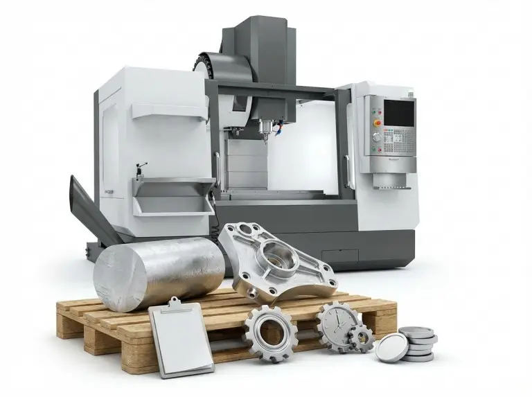

CNC machining is a method of precision manufacturing through computer-controlled machine tools. It is now widely used in aerospace, automotive, medical devices, and other fields. To achieve efficient and high-quality production in CNC machining, considerations at the design stage are critical. This CNC machining guide will detail design principles and optimization methods to help designers and engineers increase productivity, reduce costs, and ensure part quality and performance.
Basic Rules When Designing for CNC Machining Guide
Here are some basic rules to follow while designing CNC machining.
- Design items to facilitate machining with large-diameter tools to provide faster machining speeds. In addition, the use of specialized tools should be avoided as much as possible.
- Cavities should not be more than four times deeper than their breadth, as this makes machining slightly more complex.
- When creating your design, consider the primary direction your machine supports and the conventional number of axes to minimize problems.
- To avoid errors in the engraved writing, do not use sizes smaller than 20 points while machining it.
Design Restrictions for CNC Machining Guide
True, CNC machining is adaptable, yet, not all designs are possible. In other words, you must be aware of certain limitations and restrictions in order to achieve smooth machining. The two major CNC design limits are:
Tool geometry
Most CNC cutting tools have a fixed cutting length. They all have cylindrical forms and geometries. When removing materials from a workpiece, these cutting tools impart their cylindrical shape onto the workpiece. This is why, regardless of the size of the cutting tool, the internal corners of a workpiece are always radiused.
Tool Access
Tool access becomes a key challenge when working on a workpiece with a high depth-to-width ratio. This is a worry because CNC machines cut by applying cutting tools to the workpiece from above.
In other words, it would be impossible to mill a workpiece that is not accessible from the top angle. The lone exception to this rule is during undercut machining of CNC machined parts.
One way to address this tool access difficulty is to align the features of your part or component with one of the six primary directions. Furthermore, adopting a 5-axis CNC machining system with a strong workpiece holding capacity eliminates the need for tool access restrictions.
CNC Machining Design Guide
In the field of CNC machining, there is no set of standardized guides that are widely accepted. This is primarily because the industry and the machines used are constantly developing. However, several best practices and advice will help you maintain high design quality. These recommendations include:
Internal Edges
When building inner edges, ensure that the vertical corner radius is at least one-third of the cavity depth. If you follow the stated corner radii, you can use a diameter tool with the recommended cavity depth.
A slightly higher than recommended corner radius allows you to cut in a circular path rather than at a 90-degree angle. This allows you to achieve a higher-quality surface finish. If you want a 90-degree angle, use a T-bone undercut rather than reducing the corner radius.
Holes
Machinists can make holes with drill bits or end mills. Use conventional drill sizes when determining the diameter of the holes in your design. In addition, it is best to measure in metric or imperial units.
Technically, any size larger than 1 millimeter can be accomplished. Machine operators utilize reamers and boring tools to fill holes with precise tolerances. For holes smaller than 20 millimeters and requiring high accuracy, a standard diameter is recommended.
When designing parts for CNC machining, the maximum recommended depth for any hole is four times the nominal diameter, but 40 times this amount is feasible. The nominal diameter is usually ten times the ratio.
Threads
The smallest thread size used for developing CNC-machined goods is M2, while M6 or larger is frequently preferred. Machinists can reduce the risk of tap breakage by utilizing CNC threading machines to cut threads as tiny as M6.
The minimum thread length should be 1.5 times the nominal diameter, and the suggested length is three times the usual. For any thread smaller than M6, you must include an unthreaded length at the bottom of the hole that is 1.5 times the nominal diameter. Threading the hole over its length is preferable for threads larger than M6.
Cavities and Pockets
Due to the limited cutting length of end mills. Therefore, the industry-standard cavity depth for any design is four times its width. A reduced depth-to-width ratio would result in increased chip evacuation, tool deflection, and vibration.
Does your CNC design necessitate greater depths? One solution to this problem is to use a variable cavity depth and a customized instrument.
Small or Raised Text
You may need to label pieces with part numbers or business names. Adding text to the custom CNC design looks great, but it takes time to process. Electrochemical etching or laser branding is usually preferable.

Best Practices for Designing Parts Using CNC Machining Guide
Maintaining best practices and understanding the fundamentals of CNC machining assist assure high-quality parts and products. With that in mind, below are some recommended practices to follow when designing parts for CNC machining, based on the machining type.
Design for CNC Milling
CNC milling is a machining method that involves quickly removing material from raw material with round cutters to achieve the required form. Mill machines exist in a variety of designs, ranging from three to twelve axes.
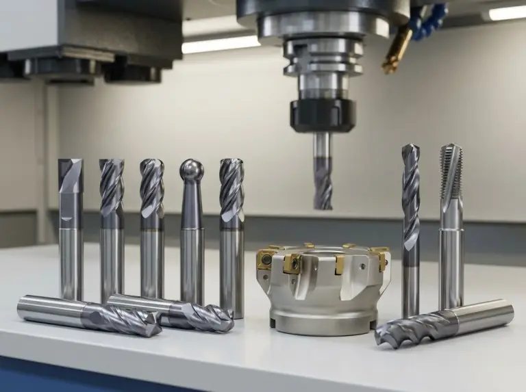
Commonly Used Cutting Tools
Consider the many tools often available for CNC milling while developing your CNC component design ideas, such as end mill cutters. If the required features and geometries can be produced using standard tools. Then the cost and lead time of the part would be greatly reduced. Therefore, consider tool standard sizes when building your design. This is because radii below the standard can lead to design problems and costs.
Avoid Sharp Internal Corners
Sharp corners cannot be achieved using a milling tool. The explanation is that the cutting tool employed in this case is round. To use a CNC mill, your corners need to have radii, which must be greater than the cutter used in making them. Ideally, the cutting tool’s diameter will be twice the radius it produces.
Filets are also required when a sloped or drafted surface encounters a vertical wall or sharp edge. Unless the surface is smooth and parallel to the tool, a square or ball end mill will always leave material between the wall and the surface below.
Avoid Deep, Narrow Slots
Lengthy tools frequently vibrate and deflect, resulting in a poor surface finish. Therefore, end mills should not cut plastics to a final depth of more than 15 times their diameter. In the cut of aluminum, it should not exceed 10 times its diameter, and in the cut of steel, it should not exceed 5 times its diameter.
For example, a slot cut on a machined steel object with a 0.5″ end mill and 0.55″ width should not be deeper than 2.75″. To account for the relationship between the internal filet radius and tool diameter, any internal radii should exceed 0.25″.
Design with the Largest Possible Internal Radius
A larger cutter removes more material per time, reducing machining time and costs. When designing, always employ the largest internal radii that are authorized. When possible, avoid radii less than 0.8mm.
Make your filets slightly larger than the endmill’s radius, such as 0.130″ (3.3mm) instead of 0.125″ (3.175mm). The mill will take a smoother route, giving the surface a finer polish.
Design for CNC Turning
CNC turning is a machining technique that produces items with axial symmetry and cylindrical shapes on a lathe. The technique entails keeping the workpiece in a revolving chuck while the cutting tool cuts it to the required shape. This machining procedure produces a smoother surface quality and tighter tolerances.
Here are some recommendations for creating a design for CNC cutting utilizing a turning machine.
Prevent Sharp Internal and External Corners
When designing for CNC machining, it is critical to eliminate sharp corners, both inside and out. Adding a radius to the internal corner helps to prevent the tool from running up a larger surface. Another method for avoiding sharp internal corners is to tilt a steep sidewall slightly. Machine contouring with a single lathe cutting tool may be more efficient because fewer operations are required.
Avoid Long and Thin Parts
Avoid using lengthy, thin-turned pieces because they tend to spin unevenly and rattle against the tool. When creating a long component, attempt to leave enough room for a center drill on the free end and use one to keep the part spinning straight. Furthermore, as a general rule, the length-to-diameter ratio should be 8:1 or less.
Avoid Thin Walls
Excessive material removal, such as milling, might put undue stress on the component. Too thin walls will also decrease rigidity. In addition, narrow walls make strict tolerances difficult to maintain. This is why you should keep the wall thickness of turned parts above 0.02 inches when designing for CNC machining.
Feature Symmetry
Every feature added to a turned part should be symmetrical around the turning axis. Adding non-axially symmetric geometry or features will necessitate more intricate machining and setups. Steps, tapers, chamfers, and curves are ideal for turning. Sometimes it is required to provide non-axially symmetric properties to a turned part, which may necessitate a distinct procedure. Even when symmetry is required, it is possible to maintain some.

Ways to Optimize Machining Paths and Reduce Costs
Through the judicious use of standard tolerances, optimizing material removal efficiencies, and selecting appropriate materials, machining paths can be effectively optimized to reduce machining time and costs while ensuring part quality and performance. This has important implications for the design and manufacturing process of CNC machining, leading to more efficient and cost-effective production.
Use of Standard Tolerances
Using standard tolerances can significantly reduce machining costs and time. Standard tolerances mean that parts do not require overly precise measurements and adjustments during the manufacturing process, thus simplifying machining steps and increasing productivity. A standard tolerance of ±0.1 mm is generally recommended to meet most design requirements without adding additional machining costs. If the design requires higher accuracy, the tolerance can be tightened to ±0.02 mm, but be aware that this will increase machining time and cost.
Choosing the right material
The choice of material has a direct impact on CNC machining design and cost. Softer materials (such as aluminum and plastics) are easier to machine than harder materials (such as steel and titanium) because they can be machined at higher cutting speeds and with less wear on the tool, resulting in increased machining speed and quality. Another advantage of soft materials is that they deform less during machining, making it easier to achieve the required tolerances and surface finish. However, it is also important to consider the end application and performance requirements when selecting a material.
Increase material removal efficiency
Optimizing the design to use standard tool sizes and reducing the number of tool changes is key to increasing material removal efficiency. Standard-sized tools should be used wherever possible, as they are not only more readily available but also less costly. In addition, the design should consider reducing the number of machining steps, for example by reducing the use of tooling and optimizing machining paths to improve efficiency. Designs can try to standardize the diameters of holes and slots so that multiple machining steps can be done with the same tool, thus reducing the number of tool changes and adjustment time.

Design Implications of Complex Geometries and Material Selection
To effectively improve the design and machining efficiency of complex geometries and to ensure the quality and functionality of your parts, Yonglihao Machinery has compiled a list of best practices and considerations to help you make better decisions.
Best Practices for Designing Complex Geometries
When designing parts with complex geometries, there are a few key things to keep in mind. First, avoid overly complex internal features, such as deep holes, narrow slots, and sharp internal corners, which can make machining more difficult and costly. Second, try to use larger internal fillets to minimize stress concentrations and increase part strength. Additionally, tool accessibility should be considered during design to ensure that all features can be machined with standard tools.
Recommended design tools include CAD and CAM software such as AutoCAD and SolidWorks, which help designers accurately create complex geometries and generate optimized machining paths. Using these tools reduces trial and error time and improves the accuracy and manufacturability of the design.
Precautions
When machining parts with complex geometries, you may encounter some common problems.
Deep holes and narrow grooves tend to cause tool breakage and machining errors. To avoid these problems, reduce the depth of each feed by cutting in stages and use specially designed tools to improve machining stability. Secondly, complex internal features may prevent the tool from fully accessing the machined surface, and special machining methods such as multi-axis CNC machines or electric discharge machining (EDM) can be considered.
Different materials behave differently in CNC machining, with harder materials such as titanium and stainless steel being more difficult and costly to machine, while softer materials such as aluminum and plastics are easier to machine. The design should be based on the application requirements of the part and consider the machining characteristics of the material. For example, aluminum is easy to machine and less expensive, but may not be suitable for applications requiring high strength.

Material selection and its design implications
By understanding the machining characteristics and design requirements of different materials, designers can optimize the design of CNC-machined parts to ensure optimal performance and cost-effectiveness.
Performance of different materials in CNC machining
The machining characteristics of different materials vary greatly in CNC machining. Commonly machined materials include aluminum, steel, titanium, and plastic. When selecting a material, comprehensive consideration should be given to the environment in which the part will be used and the functional requirements. Select the best machining material.
Aluminum: Aluminum is one of the most commonly used CNC machining materials. It is characterized by lightweight, moderate strength, and easy cutting. Aluminum also has a high thermal conductivity, which helps to dissipate heat quickly, thus reducing tool wear.
Steel: Steel has high strength and wear resistance, but is more difficult to machine. Machining steel requires stronger tools and lower cutting speeds, which increases machining time and costs.
Titanium: Titanium has very high strength and corrosion resistance, but is very difficult to machine. Titanium’s high hardness and low thermal conductivity cause rapid tool wear, so special tools and coolants are required.
Plastics: Plastic materials such as ABS and polycarbonate are easy and inexpensive to machine. However, plastics are less thermally stable and require temperature control during machining to prevent distortion.
Impact of Material Properties on Design
Material properties have a direct impact on the design of a part. Aluminum’s high thermal conductivity and ease of machining allow for more complex geometries, while the high hardness of steel and titanium limit design complexity. The flexibility and low strength of plastics require the addition of support structures during design to ensure part stability and durability. By understanding these material properties, designers can optimize their designs to maximize processing efficiency and part performance.

Conclusion
In this paper, we focus on the basic design principles, optimized machining paths, and rational material selection in the CNC machining design guide. A detailed explanation is given. Avoiding the design of deep holes, narrow slots, and sharp internal angles can help reduce machining difficulty and cost. Using large internal radii and standard tool sizes can improve material removal efficiency and reduce machining time. Choosing the right materials, such as aluminum, steel, titanium, and plastics, can meet the needs of different applications and improve part quality.
Following these design principles and optimization methods not only improves the efficiency and quality of CNC machining but also significantly reduces production costs. By properly designing and optimizing machining paths, you can ensure the durability and functionality of your parts.
If you have any CNC machining guide needs or require further technical support, please contact Yonglihao Machinery. We provide professional CNC machining parts and will offer you the best solution to ensure the successful completion of your project!
FAQ
What is CNC machining?
CNC stands for computer numerical control, which refers to the use of computers to automate machine tools. This means that the process uses computer programs to control machine tools such as lathes, milling machines, and grinders. This technology improves the accuracy, efficiency, and consistency of parts and product production.
What are the most common problems in CNC machining design?
Common problems include deep holes and narrow slots that make machining difficult and costly, sharp internal corners that are difficult to machine, and poor material selection that affects machining efficiency and quality.
How to choose the right material for CNC machining?
Material selection should be based on a combination of application and performance requirements. Aluminum is for lightweight requirements, steel for high-strength needs, titanium for high-performance parts, and plastics for low-cost applications.
What is the best way to optimize CNC machining paths?
Optimizing paths includes using standard tool sizes to reduce the number of tool changes, reducing the use of tooling to optimize the design, and using CAD/CAM software to generate optimized machining paths to improve efficiency.